“C8051F IO输出之LED显示程序”的版本间的差异
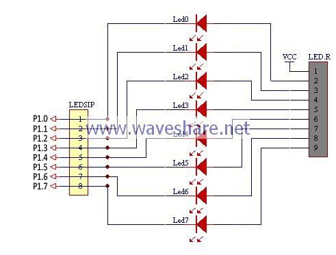
(系统功能使用C8051F单片机控制8位LED,演示C8051F单片机之“点灯术”。硬件设计关于C8051F的I/O结构及相关介绍详见Datasheet(点击查看),这里仅对作部分简单介绍,下面是AVR的I/O引脚配置表:C8051F I/O 口引脚配 ...) |
小 (文本替换 - 替换“www.waveshare.net”为“{{SERVERNAME}}”) |
||
| 第5行: | 第5行: | ||
</th></tr><tr><th class="type_483D8B" scope="col" style="line-height: 20px; font-weight: normal; border-top-style: none;" valign="top"> | </th></tr><tr><th class="type_483D8B" scope="col" style="line-height: 20px; font-weight: normal; border-top-style: none;" valign="top"> | ||
<table border="0" cellpadding="0" cellspacing="0" width="120"><tbody><tr><th align="center" bgcolor="#698192" class="white_12px_b" height="20" style="font-size: 12px; color: rgb(255, 255, 255); line-height: 20px; font-family: Arial, Helvetica, sans-serif;">硬件设计</th></tr></tbody></table> | <table border="0" cellpadding="0" cellspacing="0" width="120"><tbody><tr><th align="center" bgcolor="#698192" class="white_12px_b" height="20" style="font-size: 12px; color: rgb(255, 255, 255); line-height: 20px; font-family: Arial, Helvetica, sans-serif;">硬件设计</th></tr></tbody></table> | ||
| − | 关于C8051F的I/O结构及相关介绍详见Datasheet(<a class="Blue_2_12px_" href="http:// | + | 关于C8051F的I/O结构及相关介绍详见Datasheet(<a class="Blue_2_12px_" href="http://{{SERVERNAME}}/Left_Column/C8051F_51_Datasheets.htm" style="color: rgb(7, 66, 184); font-family: Arial, Helvetica, sans-serif;" target="_blank">点击查看 |
),这里仅对作部分简单介绍,下面是AVR的I/O引脚配置表:<table bgcolor="#DDDDDD" border="0" cellpadding="1" cellspacing="1" width="606"><tbody><tr bgcolor="#999999" class="white_14px" style="font-size: 14px; color: rgb(255, 255, 255); font-family: Arial, Helvetica, sans-serif;" valign="middle"><th colspan="6" height="25">C8051F I/O 口引脚配置表</th></tr><tr bgcolor="#FFFFFF" class="type_483D8B_12px_b" style="font-size: 12px; font-weight: bold; color: rgb(72, 61, 139); line-height: 20px; font-family: Arial, Helvetica, sans-serif;" valign="middle"><td align="center" height="20" width="79">PxMDOUT</td><td align="center" width="79">PxMDIN</td><td align="center" width="79">Px</td><td align="center" width="102">I/O 方式</td><td align="center" width="251">引脚状态说明</td></tr><tr bgcolor="#F8F8FF" class="type_483D8B" style="font-size: 12px; line-height: 20px; border-top-style: none; color: rgb(72, 61, 139);" valign="middle"><td align="center" height="20" width="79">X</td><td align="center" width="79">0</td><td align="center" width="79">X</td><td align="center" width="102">输入</td><td align="center" width="251">模拟输入</td></tr><tr bgcolor="#FFFFFF" class="type_483D8B" style="font-size: 12px; line-height: 20px; border-top-style: none; color: rgb(72, 61, 139);" valign="middle"><td align="center" height="20" width="79">0</td><td align="center" width="79">1</td><td align="center" width="79">X</td><td align="center" width="102">输入</td><td align="center" width="251">漏极开路</td></tr><tr bgcolor="#F8F8FF" class="type_483D8B" style="font-size: 12px; line-height: 20px; border-top-style: none; color: rgb(72, 61, 139);" valign="middle"><td align="center" height="20" width="79">1</td><td align="center" width="79">1</td><td align="center" width="79">X</td><td align="center" width="102">输出</td><td align="center" width="251">推挽方式</td></tr></tbody></table> | ),这里仅对作部分简单介绍,下面是AVR的I/O引脚配置表:<table bgcolor="#DDDDDD" border="0" cellpadding="1" cellspacing="1" width="606"><tbody><tr bgcolor="#999999" class="white_14px" style="font-size: 14px; color: rgb(255, 255, 255); font-family: Arial, Helvetica, sans-serif;" valign="middle"><th colspan="6" height="25">C8051F I/O 口引脚配置表</th></tr><tr bgcolor="#FFFFFF" class="type_483D8B_12px_b" style="font-size: 12px; font-weight: bold; color: rgb(72, 61, 139); line-height: 20px; font-family: Arial, Helvetica, sans-serif;" valign="middle"><td align="center" height="20" width="79">PxMDOUT</td><td align="center" width="79">PxMDIN</td><td align="center" width="79">Px</td><td align="center" width="102">I/O 方式</td><td align="center" width="251">引脚状态说明</td></tr><tr bgcolor="#F8F8FF" class="type_483D8B" style="font-size: 12px; line-height: 20px; border-top-style: none; color: rgb(72, 61, 139);" valign="middle"><td align="center" height="20" width="79">X</td><td align="center" width="79">0</td><td align="center" width="79">X</td><td align="center" width="102">输入</td><td align="center" width="251">模拟输入</td></tr><tr bgcolor="#FFFFFF" class="type_483D8B" style="font-size: 12px; line-height: 20px; border-top-style: none; color: rgb(72, 61, 139);" valign="middle"><td align="center" height="20" width="79">0</td><td align="center" width="79">1</td><td align="center" width="79">X</td><td align="center" width="102">输入</td><td align="center" width="251">漏极开路</td></tr><tr bgcolor="#F8F8FF" class="type_483D8B" style="font-size: 12px; line-height: 20px; border-top-style: none; color: rgb(72, 61, 139);" valign="middle"><td align="center" height="20" width="79">1</td><td align="center" width="79">1</td><td align="center" width="79">X</td><td align="center" width="102">输出</td><td align="center" width="251">推挽方式</td></tr></tbody></table> | ||
虽然C8051F的I/O口单独输出“1”时,可输出较大电流足已点亮一盏灯,但C8051F总的I/O输出毕竟是有限的,所以,有经验的点灯者考虑到除了点灯外可能还有其它费劲的活儿要干,会将C8051F的I/O口设计为输出“0”时点灯,输出“1”时熄灯。这种接法亦叫“灌电流接法”。 | 虽然C8051F的I/O口单独输出“1”时,可输出较大电流足已点亮一盏灯,但C8051F总的I/O输出毕竟是有限的,所以,有经验的点灯者考虑到除了点灯外可能还有其它费劲的活儿要干,会将C8051F的I/O口设计为输出“0”时点灯,输出“1”时熄灯。这种接法亦叫“灌电流接法”。 | ||
2019年11月19日 (二) 09:21的版本
<tbody></tbody>
使用C8051F单片机控制8位LED,演示C8051F单片机之“点灯术”。 | |||||||||||||||||||||||||||
|---|---|---|---|---|---|---|---|---|---|---|---|---|---|---|---|---|---|---|---|---|---|---|---|---|---|---|---|
<tbody></tbody>
关于C8051F的I/O结构及相关介绍详见Datasheet(<a class="Blue_2_12px_" href="http://wiki.diustou.com/Left_Column/C8051F_51_Datasheets.htm" style="color: rgb(7, 66, 184); font-family: Arial, Helvetica, sans-serif;" target="_blank">点击查看 ),这里仅对作部分简单介绍,下面是AVR的I/O引脚配置表:<tbody></tbody>
虽然C8051F的I/O口单独输出“1”时,可输出较大电流足已点亮一盏灯,但C8051F总的I/O输出毕竟是有限的,所以,有经验的点灯者考虑到除了点灯外可能还有其它费劲的活儿要干,会将C8051F的I/O口设计为输出“0”时点灯,输出“1”时熄灯。这种接法亦叫“灌电流接法”。
| |||||||||||||||||||||||||||
<tbody></tbody>
下面部分从TXT拷出,拷到网页,代码部分缺省了很多空格,比较凌乱,请谅解! //目标系统: 基于C8051F单片机 //应用软件: Silicon IDE / Keil /*01010101010101010101010101010101010101010101010101010101010101010101 实验内容: 点灯,LED灯按顺序从第一盏到第八盏灯依次点亮。 硬件连接: 将P1口与8位LED指示灯相连。 注意事项: (1)若有加载库程序,请将光盘根目录下的“library”下的“C8051F”文件夹拷到D盘 (2)请详细阅读:光盘根目录下的“说明书首页.htm”里的相应产品说明 10101010101010101010101010101010101010101010101010101010101010101010*/
void main(void) { uchar a,i; PCA0MD &= ~0x40; //Clear watchdog timer enable clock_internal(); P1MDOUT = 0xFF; XBR1 = 0x40; a = 0xFF; while(1) { for(i=0;i<9;i++) { P1 = ~a; a <<= 1; delay_ms(500); } a = 0xFF; } } | |||||||||||||||||||||||||||
<tbody></tbody>
本节的目的在于学习AVR的IO输出功能,对于AVR来说,它和传统的51单片机不同,需要设置IO引脚方向。 作如下调试: (1)改变IO方向,即将“a = 0xFF;”改为“a = 0x00;”,观察现象。 (2)将语句:delay_ms(500);改为语句:delay_ms(100);可以看到LED闪的更快 | |||||||||||||||||||||||||||
