“实验二十九:MAX7219点阵实验”的版本间的差异
来自丢石头百科
Yousimaier17(讨论 | 贡献) (创建页面,内容为“首页 == Arduino == === 实验现象 === * 模块上电循环显示图案。 === 注意事项 === *接线的时候,注意…”) |
Yousimaier17(讨论 | 贡献) (→电路连接) |
||
| (未显示同一用户的2个中间版本) | |||
| 第1行: | 第1行: | ||
| − | [[Basic Experiment Kits For Arduino | + | *[[Basic Experiment Kits For Arduino]] |
| + | *[[Basic Experiment Kits For Raspberry Pi]] | ||
== Arduino == | == Arduino == | ||
=== 实验现象 === | === 实验现象 === | ||
| 第10行: | 第11行: | ||
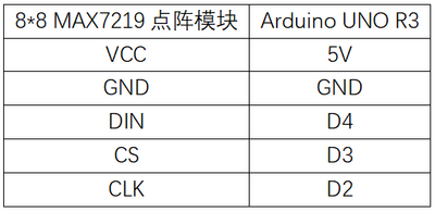
=== 电路连接 === | === 电路连接 === | ||
*[[File:实验二十九:MAX7219点阵实验_接线.png|400px]] | *[[File:实验二十九:MAX7219点阵实验_接线.png|400px]] | ||
| − | + | ||
=== 主要程序 === | === 主要程序 === | ||
<pre> | <pre> | ||
| − | byte b8[8]= {0x3C,0x00,0x00,0x00,0x00,0x18,0x3C,0x18}; | + | #include "LedControl.h" |
| + | int DIN = 4; | ||
| + | int CS = 3; | ||
| + | int CLK = 2; | ||
| + | |||
| + | LedControl lc=LedControl(DIN,CLK,CS,0); | ||
| + | |||
| + | void setup(){ | ||
| + | lc.shutdown(0,false); | ||
| + | lc.setIntensity(0,15); //Adjust the brightness maximum is 15 | ||
| + | lc.clearDisplay(0); | ||
| + | } | ||
| + | |||
| + | void loop(){ | ||
| + | |||
| + | //Facial Expression | ||
| + | byte smile[8]= {0x3C,0x42,0xA5,0x81,0xA5,0x99,0x42,0x3C}; | ||
| + | byte neutral[8]= {0x3C,0x42,0xA5,0x81,0xBD,0x81,0x42,0x3C}; | ||
| + | byte sad[8]= {0x3C,0x42,0xA5,0x81,0x99,0xA5,0x42,0x3C}; | ||
| + | |||
| + | //Arrow | ||
| + | byte arrow_up[8]= {0x18,0x3C,0x7E,0xFF,0x18,0x18,0x18,0x18}; | ||
| + | byte arrow_down[8]= {0x18,0x18,0x18,0x18,0xFF,0x7E,0x3C,0x18}; | ||
| + | |||
| + | |||
| + | //Alternate Pattern | ||
| + | byte d1[8]= {0xAA,0x55,0xAA,0x55,0xAA,0x55,0xAA,0x55}; | ||
| + | byte d2[8]= {0x55,0xAA,0x55,0xAA,0x55,0xAA,0x55,0xAA}; | ||
| + | |||
| + | //Moving car | ||
| + | byte b1[8]= {0x00,0x00,0x00,0x00,0x18,0x3C,0x18,0x3C};//8*8LED点阵 取模软件生成 | ||
| + | byte b2[8]= {0x00,0x00,0x00,0x18,0x3C,0x18,0x3C,0x00}; | ||
| + | byte b3[8]= {0x00,0x00,0x18,0x3C,0x18,0x3C,0x00,0x00}; | ||
| + | byte b4[8]= {0x00,0x18,0x3C,0x18,0x3C,0x00,0x00,0x00}; | ||
| + | byte b5[8]= {0x18,0x3C,0x18,0x3C,0x00,0x00,0x00,0x00}; | ||
| + | byte b6[8]= {0x3C,0x18,0x3C,0x00,0x00,0x00,0x00,0x18}; | ||
| + | byte b7[8]= {0x18,0x3C,0x00,0x00,0x00,0x00,0x18,0x3C}; | ||
| + | byte b8[8]= {0x3C,0x00,0x00,0x00,0x00,0x18,0x3C,0x18}; | ||
| + | |||
| + | |||
//Moving car | //Moving car | ||
printByte(b1); | printByte(b1); | ||
| 第20行: | 第60行: | ||
delay(50); | delay(50); | ||
printByte(b3); | printByte(b3); | ||
| − | delay(50); | + | delay(50); |
| − | . | + | printByte(b4); |
| + | delay(50); | ||
| + | printByte(b5); | ||
| + | delay(50); | ||
| + | printByte(b6); | ||
| + | delay(50); | ||
| + | printByte(b7); | ||
| + | delay(50); | ||
| + | printByte(b8); | ||
| + | delay(50); | ||
| + | |||
| + | //alternate pattern | ||
| + | printByte(d1); | ||
| + | delay(100); | ||
| + | |||
| + | printByte(d2); | ||
| + | delay(100); | ||
| + | |||
| + | //Arrow | ||
| + | printByte(arrow_up); | ||
| + | delay(2000); | ||
| + | |||
| + | printByte(arrow_down); | ||
| + | delay(2000); | ||
| + | |||
| + | |||
| + | //Facial Expression | ||
| + | printByte(smile); | ||
| + | |||
| + | delay(1000); | ||
| + | |||
| + | printByte(neutral); | ||
| + | |||
| + | delay(1000); | ||
| + | |||
| + | printByte(sad); | ||
| + | |||
| + | delay(1000); | ||
| + | |||
| + | |||
| + | } | ||
| + | |||
| + | void printByte(byte character []) | ||
| + | { | ||
| + | int i = 0; | ||
| + | for(i=0;i<8;i++) | ||
| + | { | ||
| + | lc.setRow(0,i,character[i]); | ||
| + | } | ||
| + | } | ||
</pre> | </pre> | ||
== 树莓派 == | == 树莓派 == | ||
| − | |||
| − | |||
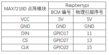
=== 电路连接 === | === 电路连接 === | ||
| − | * | + | *[[File:实验二十九:MAX7219点阵实验_接线1.png|600px]] |
| + | |||
=== 程序运行 === | === 程序运行 === | ||
| − | |||
==== Python ==== | ==== Python ==== | ||
| + | * 安装gpiozero库 | ||
| + | **可以使下面命令来安装该库 | ||
| + | <pre> | ||
| + | sudo apt update | ||
| + | sudo apt install python3-gpiozero | ||
| + | </pre> | ||
| + | :*其它树莓派上的系统可以使下面命令来安装该库: | ||
| + | <pre> | ||
| + | sudo pip3 install gpiozero | ||
| + | </pre> | ||
| + | :*运行以下语句可以查看树莓派GPIO口定义 | ||
| + | <pre> | ||
| + | pinout | ||
| + | </pre> | ||
| + | *下载树莓派参考例程,将文件解压后拷贝放在用户名目录下,运行 | ||
| + | <pre> | ||
| + | cd raspberrypi/29/python_gpiozero | ||
| + | python MAX7219.py | ||
| + | </pre> | ||
| + | *此时可看见树莓派在正确运行程序,若想退出,按ctrl+C即可 | ||
| + | *指令说明:'''gpiozero.OutputDevice(pin, active_high, initial_value)''' | ||
| + | **主要参数: | ||
| + | ***pin: GPIO口编号, | ||
| + | *** active_high: 内部上下拉电阻设置, | ||
| + | ****设置为True(默认)时,on()将引脚设置为High,off()将引脚设置为LOW。 | ||
| + | ****设置为Flase时,on()将引脚设置为LOW,off()将引脚设置为High。 | ||
| + | ***initial_value: | ||
| + | ****如果为False(默认值),则所有LED初始状态为关闭。 | ||
| + | ****如果为None,则所有LED初始状态不稳定。 | ||
| + | ****如果为True,则所有LED初始状态为关闭打开。 | ||
| + | *更多指令请查看[https://gpiozero.readthedocs.io/en/latest/installing.html gpiozero文档] | ||
| − | + | == 例程下载 == | |
| + | *[[:File:Basic Experiment Kits For Arduino.zip|Arduino例程]] | ||
| + | * [[:File:Basic Experiment Kits For Raspberry Pi.zip|树莓派5例程 python]] | ||
== 相关例程 == | == 相关例程 == | ||
{{Arduino and Raspberry Pi Case}} | {{Arduino and Raspberry Pi Case}} | ||
2024年12月6日 (五) 12:05的最新版本
Arduino
实验现象
- 模块上电循环显示图案。
注意事项
- 接线的时候,注意方向,左侧排针为输入端(1088AS丝印在PCB板上方)
- LED的方向要注意,如果显示不正常,请转变下安插的方向。
电路连接
主要程序
#include "LedControl.h"
int DIN = 4;
int CS =  3;
int CLK = 2;

LedControl lc=LedControl(DIN,CLK,CS,0);

void setup(){
 lc.shutdown(0,false);
 lc.setIntensity(0,15);      //Adjust the brightness maximum is 15
 lc.clearDisplay(0);
}

void loop(){

    //Facial Expression
    byte smile[8]=   {0x3C,0x42,0xA5,0x81,0xA5,0x99,0x42,0x3C};
    byte neutral[8]= {0x3C,0x42,0xA5,0x81,0xBD,0x81,0x42,0x3C};
    byte sad[8]=   {0x3C,0x42,0xA5,0x81,0x99,0xA5,0x42,0x3C};

    //Arrow
    byte arrow_up[8]= {0x18,0x3C,0x7E,0xFF,0x18,0x18,0x18,0x18};
    byte arrow_down[8]= {0x18,0x18,0x18,0x18,0xFF,0x7E,0x3C,0x18};


    //Alternate Pattern
    byte d1[8]= {0xAA,0x55,0xAA,0x55,0xAA,0x55,0xAA,0x55};
    byte d2[8]= {0x55,0xAA,0x55,0xAA,0x55,0xAA,0x55,0xAA};

    //Moving car
    byte b1[8]= {0x00,0x00,0x00,0x00,0x18,0x3C,0x18,0x3C};//8*8LED点阵 取模软件生成
    byte b2[8]= {0x00,0x00,0x00,0x18,0x3C,0x18,0x3C,0x00};
    byte b3[8]= {0x00,0x00,0x18,0x3C,0x18,0x3C,0x00,0x00};
    byte b4[8]= {0x00,0x18,0x3C,0x18,0x3C,0x00,0x00,0x00};
    byte b5[8]= {0x18,0x3C,0x18,0x3C,0x00,0x00,0x00,0x00};
    byte b6[8]= {0x3C,0x18,0x3C,0x00,0x00,0x00,0x00,0x18};
    byte b7[8]= {0x18,0x3C,0x00,0x00,0x00,0x00,0x18,0x3C};
    byte b8[8]= {0x3C,0x00,0x00,0x00,0x00,0x18,0x3C,0x18};


//Moving car
    printByte(b1);
    delay(50);
    printByte(b2);
    delay(50);
    printByte(b3);
    delay(50);
    printByte(b4);
    delay(50);
    printByte(b5);
    delay(50);
    printByte(b6);
    delay(50);
    printByte(b7);
    delay(50);
    printByte(b8);
    delay(50);

//alternate pattern
    printByte(d1);
    delay(100);

    printByte(d2);
    delay(100);

//Arrow
    printByte(arrow_up);
    delay(2000);

    printByte(arrow_down);
    delay(2000);


//Facial Expression
    printByte(smile);

    delay(1000);

    printByte(neutral);

    delay(1000);

    printByte(sad);

    delay(1000);


}

void printByte(byte character [])
{
  int i = 0;
  for(i=0;i<8;i++)
  {
    lc.setRow(0,i,character[i]);
  }
}
树莓派
电路连接
程序运行
Python
- 安装gpiozero库
- 可以使下面命令来安装该库
sudo apt update
sudo apt install python3-gpiozero
- 其它树莓派上的系统可以使下面命令来安装该库:
sudo pip3 install gpiozero
- 运行以下语句可以查看树莓派GPIO口定义
pinout
- 下载树莓派参考例程,将文件解压后拷贝放在用户名目录下,运行
cd raspberrypi/29/python_gpiozero
python MAX7219.py
- 此时可看见树莓派在正确运行程序,若想退出,按ctrl+C即可
- 指令说明:gpiozero.OutputDevice(pin, active_high, initial_value)
- 主要参数:
- pin: GPIO口编号,
- active_high: 内部上下拉电阻设置,
- 设置为True(默认)时,on()将引脚设置为High,off()将引脚设置为LOW。
- 设置为Flase时,on()将引脚设置为LOW,off()将引脚设置为High。
- initial_value:
- 如果为False(默认值),则所有LED初始状态为关闭。
- 如果为None,则所有LED初始状态不稳定。
- 如果为True,则所有LED初始状态为关闭打开。
- 主要参数:
- 更多指令请查看gpiozero文档

