Difference between revisions of "矩阵键盘"
From Diustou Wiki
Yousimaier17 (talk | contribs) |
Yousimaier17 (talk | contribs) |
||
| Line 1: | Line 1: | ||
{{Product | {{Product | ||
| − | |images=[[File: | + | |images=[[File:矩阵键盘_封面图.png|400px]] |
|categories= | |categories= | ||
{{Category|Keyboard}} | {{Category|Keyboard}} | ||
Revision as of 15:52, 10 January 2025
| ||||||||||||||||||||||
| ||||||||||||||||||||||
| ||||||||||||||||||||||
Product Overview
A matrix keyboard serves as an external device for microcontrollers. When a large number of keys are required, to reduce the occupation of I/O ports and improve the utilization rate of the microcontroller, the keys are usually arranged in a matrix form. In a matrix keyboard, each horizontal line is connected to each vertical line through a key, allowing an 8-bit port of the microcontroller to control 4*4=16 matrix keys, which is double the number compared to directly controlling the keys with ports. The difference becomes more pronounced as the number of lines increases.
Scanning Principle
- The structure of a matrix keyboard is slightly more complex than that of an independent keyboard, and the recognition by the microcontroller is also more complicated. There are two scanning methods for matrix keyboards: row-column scanning and row/column-by-row scanning. Row-column scanning, also known as the line inversion method, is suitable for when the matrix keyboard is controlled by consecutive I/O ports of the microcontroller; row/column-by-row scanning is suitable for when the matrix keyboard is connected to any I/O ports of the microcontroller. Row-column scanning is more commonly used in practical microcontroller applications.
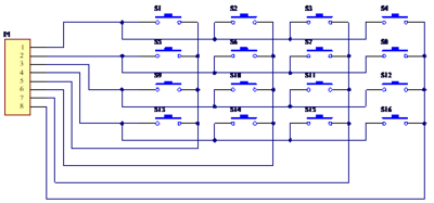
- Taking a 4*4 matrix keyboard as an example, the four row lines (starting from the first row) are connected to P1.0-P1.3 of the microcontroller, and the four column lines (starting from the first column) are connected to P1.4-P1.7.
- Row-Column Scanning Method
- Set the high four bits of port P1 to output high level and the low four bits to output low level. At this time, the column lines are pulled high and the row lines are pulled low. If a key is pressed, the level of a certain column will be pulled low. At this point, read the level of the high four bits (four columns) of port P1. If the read value is not all high, it indicates that a key is pressed, and the column can be determined based on the read value. Then, set the high four bits of port P1 to output low level and the low four bits to output high level, and read the level of the low four bits (four rows) of port P1. At this time, the read value is no longer all high, and the row can be determined based on the read value. By combining the results of the two readings, the key value of the current key can be obtained, thereby determining the position of the pressed key.
- Row/Column-by-Row Scanning Method
- The essence of the row/column-by-row scanning method is similar to the row-column scanning method, which is to output low level to a certain row/column and high level to the remaining seven. At this time, read the level change. If it is low, it indicates that a key is pressed, and the position of the pressed key can be judged based on the read key value.
- The specific operation is as follows: set the first row to low level and the remaining three rows and four columns to high level. Read the data of the column lines. If the column lines are not all high, it indicates that a key in the first row is pressed, and the specific column of the first row where the key is pressed can be judged based on the read data; if the column lines are all high, set the second row to low level, and the remaining three rows and four columns to high level, read the data of the column lines, and judge whether a key is pressed. Repeat the above actions, and so on.
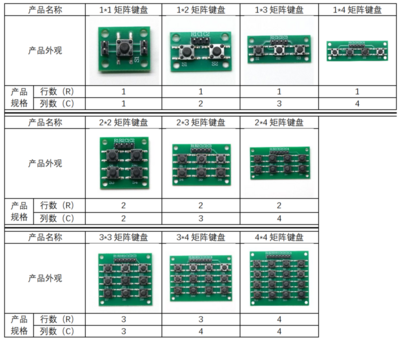
Product Model
Circuit Diagram
Program
FAQ
|

