Difference between revisions of "TTL Recorder"
From Diustou Wiki
Yousimaier17 (talk | contribs) |
Yousimaier17 (talk | contribs) |
||
| Line 36: | Line 36: | ||
== Usage Instructions == | == Usage Instructions == | ||
*When the board is powered on for the first time (i.e., there is no ulog_config.txt on the SD card) or if the file format is incorrect, a new ulog_config.txt configuration file will be automatically created upon power-up. | *When the board is powered on for the first time (i.e., there is no ulog_config.txt on the SD card) or if the file format is incorrect, a new ulog_config.txt configuration file will be automatically created upon power-up. | ||
| − | + | '''Contents of ulog_config.txt''':(Do not change the order, do not add spaces afterward, do not alter the preceding characters; except for the baud rate, other settings can be modified with the values specified in parentheses.) | |
[ulog_fw]:220620A # Current version number | [ulog_fw]:220620A # Current version number | ||
[write_raw(0,1)]:0 # Whether to write RAW data to the SD card, i.e., whether to generate a .bin file. Set to 0 to not save, default is 0. | [write_raw(0,1)]:0 # Whether to write RAW data to the SD card, i.e., whether to generate a .bin file. Set to 0 to not save, default is 0. | ||
Revision as of 17:00, 15 January 2025
| ||||||||||||||||||||||
| ||||||||||||||||||||||
| ||||||||||||||||||||||
| ||||||||||||||||||||||
Contents
Product Overview
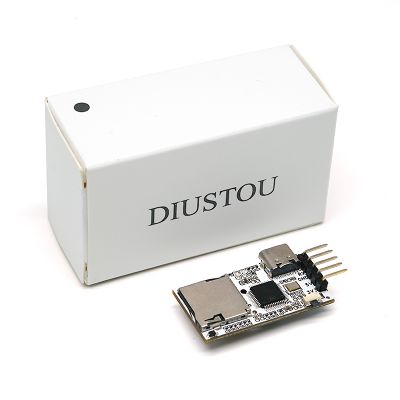
- This module is an intelligent storage module that can store data received via the UART interface in TXT format onto an SD card, serving the purpose of recording serial port data. It is suitable for applications such as environmental monitoring, flow data logging, drone data recording, and various sensor data logging. It can also be used with microcontroller devices like Arduino, Raspberry Pi, and STM32 for development, debugging, and product testing.
Product Description
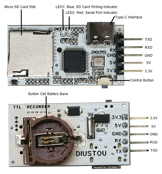
- Power Supply Voltage: 3.3V or 5V. Can be powered via Type-C interface or pin header.
- Onboard Type-C interface and UART interface.
- Enter USB drive mode via the Type-C interface.
- Transmit data via the UART interface.
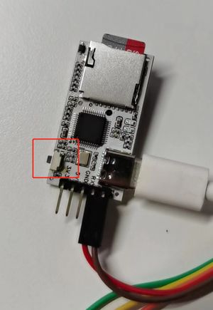
- Onboard control button for switching the module to USB drive mode and RTC time setting mode.
- Onboard dual LED indicators to display system operating status.
- Onboard Micro SD card slot, supporting FAT32 and EXFAT formats, with a maximum capacity of 128GB.
- Onboard CR1220 button battery holder, supporting RTC for real-time data collection time recording.
- Supported Baud Rates: 56000bps – 2Mbps, default is 115200.
- Read files from the TF card without the need for a USB card reader and save them to a specified directory on the computer.
- Capable of storing files in other formats such as video and audio.
- Product Dimensions: 38mm*19mm.
Pin Description
Usage Instructions
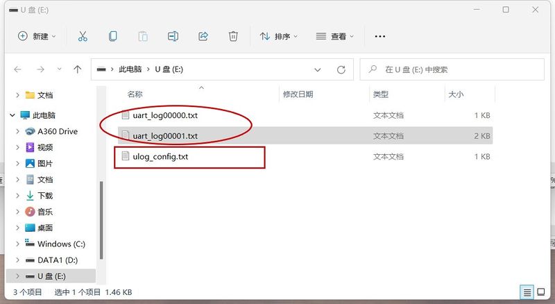
- When the board is powered on for the first time (i.e., there is no ulog_config.txt on the SD card) or if the file format is incorrect, a new ulog_config.txt configuration file will be automatically created upon power-up.
 Contents of ulog_config.txt:(Do not change the order, do not add spaces afterward, do not alter the preceding characters; except for the baud rate, other settings can be modified with the values specified in parentheses.)
 [ulog_fw]:220620A                 # Current version number
 [write_raw(0,1)]:0                # Whether to write RAW data to the SD card, i.e., whether to generate a .bin file. Set to 0 to not save, default is 0.
 [write_time(0,1)]:1               # Whether to write time-stamped data to the SD card, i.e., whether to generate a .txt file. Set to 1 to save, default is 1.
 [uart_baud]:1500000               # Baud rate
 [uart_dataLength(8,9)]:8          # Data length
 [uart_Direction(MSB,LSB)]:LSB     # Least Significant Bit first or Most Significant Bit first
 [uart_Parity(None,Even,Odd)]:None # Parity bit
 [uart_stopBit(1,2)]:1             # Stop bit
- Each time the board powers on and enters ULOG printing mode, a new uart_log00000.txt file will be automatically created on the SD card to receive data from the serial port. The number 00000 will increment upwards.
ULOG Printing Mode
- Insert the SD card while the power is off, and cross-connect the TTL Recorder module with the serial port module (TXD-RXD, RXD-TXD, 3.3V/5V-3.3V/5V, GND-GND (or power via the Type-C interface)). Do not press the control button before powering on; powering on will enter ULOG printing mode. At this point, the red LED will flash once, and the blue LED will flash quickly. If the SD card is not inserted when powering on, both the red and blue LEDs will remain on.
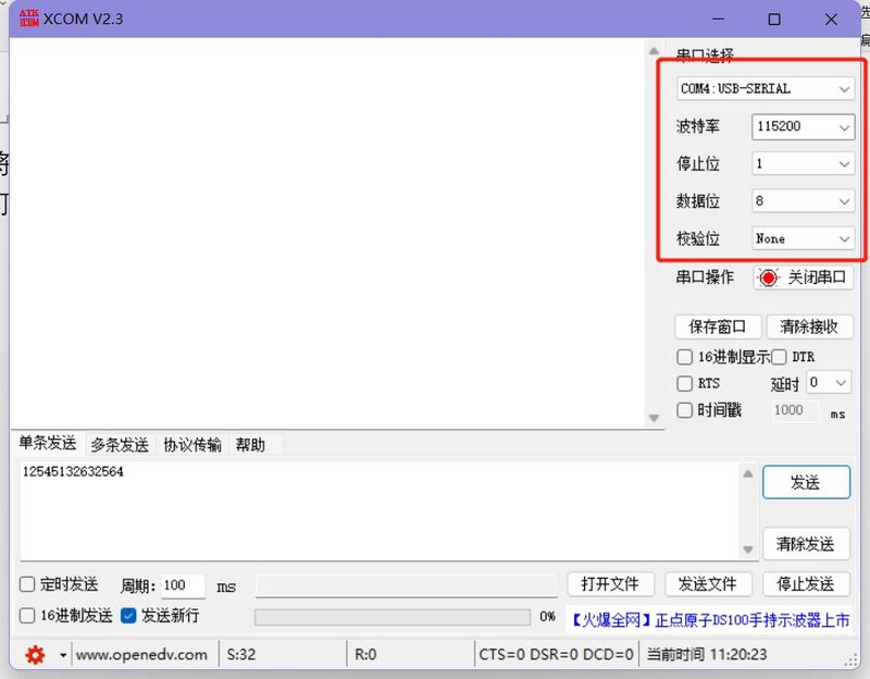
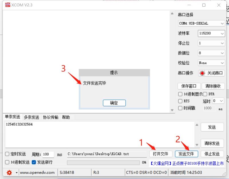
- After inserting the serial port module into the computer, open the serial port debugging assistant, select the corresponding COM port, and configure it according to the settings in the configuration file (for the first power-on, configure it as shown in the figure below). Once configured, open the serial port, click send, and each successful data transmission will cause the red LED on the TTL Recorder to flash once (the blue LED may also flash synchronously). If the flashing is abnormal, please check the configuration.
RAW Function
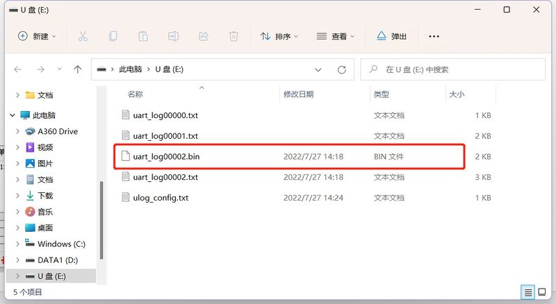
- Open the ulog_config.txt file and modify: [write_raw(0,1)]:0 -> [write_raw(0,1)]:1. After successful modification, in addition to storing the received data in the uart_log0000x.txt file, the module will also create a uart_log0000x.bin file on the SD card, which contains no timestamps and only the raw received data.
- Testing: Save the modified ulog_config.txt file and power on to enter ULOG printing mode. Set the corresponding values in the serial port assistant (the same as those in the configuration file), open the serial port, click to open a file, select the file/image to be transmitted (.txt or .jpg format, other formats are also acceptable), and then send the file. After sending, enter USB drive mode. At this point, you will notice that there is an additional .bin file on the USB drive. You can copy it to the desktop, change the file extension to match the transmitted file, and open the modified file to check if the content matches the transmitted file.
USB Drive Mode
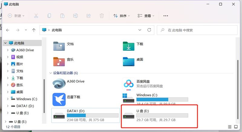
- Insert the SD card while the power is off, press and hold the control button, insert the Type-C cable, and release the button after the board powers on to enter USB drive mode. At this point, the red LED will enter a breathing light state, and the blue LED will flash quickly. Once the blue LED goes out, the USB drive will appear on the PC.
- After entering USB drive mode, you can view the contents of the SD card through My Computer -> USB drive without the need for a USB card reader or inserting/removing the SD card.
RTC Time Setting Mode
- Insert the SD card and button battery while the power is off, and cross-connect the TTL Recorder module with the serial port module (TXD - RXD, RXD - TXD). Press and hold the control button. There are two ways to power on:
- Insert the Type-C cable, release the button after the board powers on to enter RTC time setting mode. At this point, the red LED will enter a breathing light state, and the blue LED will flash quickly.
- Power through the serial port, release the button after the board powers on to enter RTC time setting mode. At this point, the red LED will enter a breathing light state, and the blue LED will remain off.
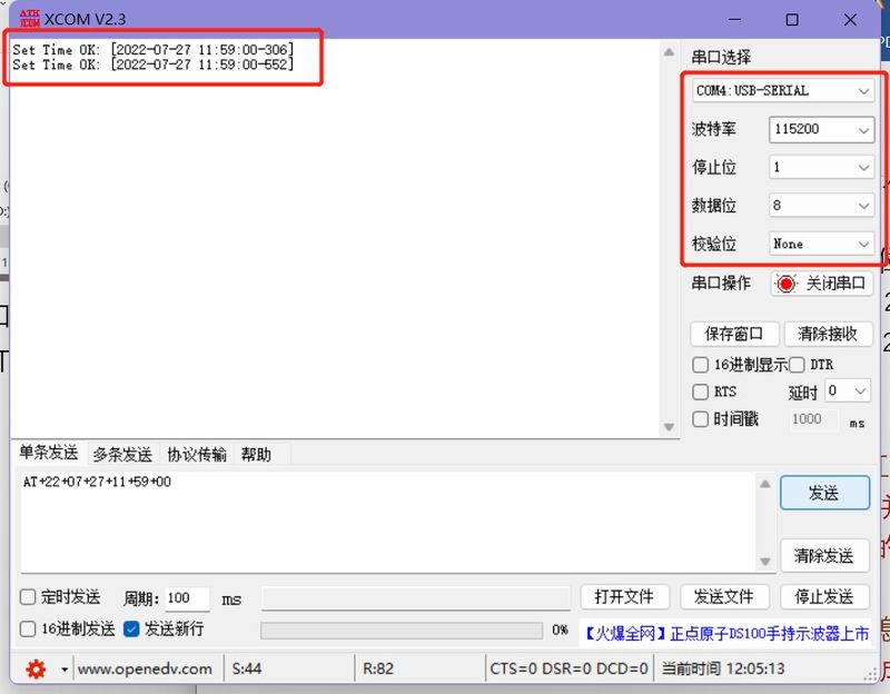
- Open the serial port debugging assistant and send the AT+22+07+27+11+59+00 command via the UART port with a configuration of baud rate 115200, 8 data bits, 1 stop bit, no parity bit to set the time. This command sets the time to 2022-07-27 11:59:00. If the configuration is successful, it will return Set Time OK: [2022-07-27 11:59:00-xxx].
Related Software
Precautions
- When there is printing or during power-on, if the blue LED is flashing and the red LED is on steadily, do not remove the card or disconnect the power, as this may damage some data.
- Insert or remove the SD card while the module is powered off.
- The RTC settings of the module can only be configured by sending commands via the UART port.
- The module must be connected via a Type-C cable to enter USB drive mode.
- To maintain the RTC clock after power loss, an RTC battery must be installed, with a battery voltage of approximately 3V.
FAQ
|
