Difference between revisions of "Basic Pack For Arduino"
From Diustou Wiki
Yousimaier17 (talk | contribs) |
Yousimaier17 (talk | contribs) |
||
| (2 intermediate revisions by the same user not shown) | |||
| Line 6: | Line 6: | ||
|features= | |features= | ||
*Basic Pack For Arduino | *Basic Pack For Arduino | ||
| + | |related= | ||
| + | * [[Basic Pack For Arduino]] | ||
| + | * [[Basic Pack Plus For Arduino]] | ||
| + | * [[Basic Experiment Kits For Arduino]] | ||
| + | * [[Basic Experiment Kits For Raspberry Pi]] | ||
}} | }} | ||
| Line 71: | Line 76: | ||
*A PNP transistor is composed of two P-type semiconductors sandwiching an N-type semiconductor, hence its name. It can also be described as a transistor where current flows into the emitter (E). In a PNP transistor, the emitter has the highest potential, the collector has the lowest potential, and UBE < 0. | *A PNP transistor is composed of two P-type semiconductors sandwiching an N-type semiconductor, hence its name. It can also be described as a transistor where current flows into the emitter (E). In a PNP transistor, the emitter has the highest potential, the collector has the lowest potential, and UBE < 0. | ||
:[[File:Basic Pack For Arduino_三极管_结构.png|400px]] | :[[File:Basic Pack For Arduino_三极管_结构.png|400px]] | ||
| − | *Pin description: [[File: | + | *Pin description: [[File:Pack For Arduino_三极管_引脚.png|400px]] |
*Polarity judgment: The method for determining the polarity of a transistor is based on the fact that the basic structure of a transistor consists of two back-to-back PN junctions. Utilizing the unidirectional conductivity of PN junctions and the resistance range of a multimeter, we can distinguish the polarity or type of the transistor. | *Polarity judgment: The method for determining the polarity of a transistor is based on the fact that the basic structure of a transistor consists of two back-to-back PN junctions. Utilizing the unidirectional conductivity of PN junctions and the resistance range of a multimeter, we can distinguish the polarity or type of the transistor. | ||
**Determining the base of the transistor: For an NPN transistor, connect the black probe to one electrode and the red probe to the other two electrodes separately. If the measured resistance values are both small, and after swapping the probes, the measured resistance values are both large, it can be concluded that the electrode connected to the black probe during the first measurement is the base. If the measured resistance values are significantly different, the electrode connected to the black probe during the first measurement is not the base, and another electrode should be tested. | **Determining the base of the transistor: For an NPN transistor, connect the black probe to one electrode and the red probe to the other two electrodes separately. If the measured resistance values are both small, and after swapping the probes, the measured resistance values are both large, it can be concluded that the electrode connected to the black probe during the first measurement is the base. If the measured resistance values are significantly different, the electrode connected to the black probe during the first measurement is not the base, and another electrode should be tested. | ||
Latest revision as of 16:28, 22 January 2025
| |||||||||||||||||||
| |||||||||||||||||||
| |||||||||||||||||||
| |||||||||||||||||||

Contents
- 1 Product Description
- 2 Instructions for Use
- 3 Related Examples
Product Description

Instructions for Use
Breadboard
- The breadboard has two columns of power rails on the left and right sides, respectively. Each column consists of five holes in a group. The holes within the same group and between different groups are interconnected, but the holes between columns are not interconnected.
- The holes in the middle section are divided into left and right sides by the central groove. Each side has five holes in a row forming a group, with the holes within the same group being interconnected, but the holes between rows are not interconnected.

Color-coded Resistor
- Resistance Identification
- The resistance can be measured using the resistance range of a multimeter.
- Color-coding reading method: For a five-band resistor, the first, second, and third bands represent the three significant digits of the resistance value; the fourth band represents the multiplier; the fifth band represents the tolerance. If the fifth band is black, it typically indicates a wirewound resistor. If the fifth band is white, it usually indicates a fuse resistor. If the resistor body only has a single black band in the middle, it represents a zero-ohm resistor.
- For a five-band resistor, the gap between the fifth and fourth bands is wider than the gap between the first and second bands.
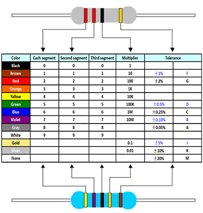
- Example:
- The resistor kit includes nine different resistance values. It is recommended to confirm the resistance values before use to avoid damaging components due to incorrect resistance.


Electrolytic Capacitor
- An electrolytic capacitor is a type of capacitor where the positive electrode (anode) is made of metal foil (aluminum or tantalum), and the dielectric is a metal oxide film (aluminum oxide or tantalum pentoxide) tightly adhered to the positive electrode. The negative electrode (cathode) is composed of conductive material, electrolyte (which can be liquid or solid), and other materials. The term "electrolytic capacitor" is derived from the fact that the electrolyte is a major component of the cathode. It is crucial not to reverse the polarity when connecting an electrolytic capacitor.
- Polarized electrolytic capacitors are commonly used in power supply circuits or intermediate and low-frequency circuits for power filtering, decoupling, signal coupling, setting time constants, blocking DC, and other purposes. They are generally not suitable for AC power supply circuits. When used as a filter capacitor in a DC power supply circuit, the anode (positive electrode) should be connected to the positive terminal of the power supply voltage, and the cathode (negative electrode) should be connected to the negative terminal of the power supply voltage. Reversing the connections can damage the capacitor.
- Polarity of Electrolytic Capacitors: Observe that the side of the electrolytic capacitor marked with a "-" indicates the negative electrode, and a "+" indicates the positive electrode. If the electrolytic capacitor does not have polarity markings, the polarity can also be determined by the length of its leads, with the longer lead being the positive electrode and the shorter lead being the negative electrode.
- The electrolytic capacitors included in this kit are: 10uf/25V and 100uf/25V.
Ceramic Capacitor
- A ceramic capacitor is a type of capacitor made with ceramic material as the dielectric, coated with a layer of metal film on the ceramic surface, and then sintered at high temperatures to form the electrodes. It is commonly used in high-stability oscillator circuits as a circuit, bypass capacitor, and decoupling capacitor.
Ceramic capacitors do not have polarity.
- Capacitance Identification: Ceramic capacitors often have three digits printed on their exterior to indicate the capacitance value. The first two digits represent the significant digits of the nominal capacitance, and the third digit indicates the number of zeros following the significant digits, all in units of pF. There is a special case in this notation where, when the third digit is "9", it represents multiplying the significant digits by 10 to the power of -1 to obtain the capacitance value.
- Example:
102 represents a nominal capacitance of 1010² pF = 1000 pF 103 represents a nominal capacitance of 1010³ pF = 10000 pF = 10 nF 229 represents a nominal capacitance of 2210^(-1) pF = 2.2 pF And so on.
F5 LED
Single-color and Multicolor (RGB) LEDs
- A light-emitting diode (LED), like a conventional diode, consists of a PN junction and exhibits unidirectional conductivity. When a forward voltage is applied to the LED, holes injected from the P region into the N region and electrons injected from the N region into the P region recombine with electrons in the N region and holes in the P region, respectively, within a few micrometers of the PN junction, producing spontaneous emission of light. Different semiconductor materials have different energy states for electrons and holes. When electrons and holes recombine, they release varying amounts of energy. The more energy released, the shorter the wavelength of the emitted light.
- The reverse breakdown voltage of an LED is greater than 5 volts. Its forward voltage-current characteristic curve is steep, so a current-limiting resistor must be connected in series to control the current through the diode.
- The longer lead of the LED is the positive (anode), and the shorter lead is the negative (cathode). In practical applications, the circuit current should flow from the positive lead (anode) of the LED to the negative lead (cathode).
RGB LED
- The display principle of an RGB LED is based on the primary color principle, where the displayed color is a mixture of red, green, and blue light. Unlike conventional LEDs, an RGB LED package contains three LEDs: one red, one green, and one blue. By controlling the brightness of each LED, a full-color effect can be achieved.
- In practical use, each of the three LED control pins needs to be connected to a control pin through a current-limiting resistor.
- Pin description:
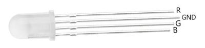
- The RGB LED provided in this kit is a common-cathode LED.

Buzzer
- An active buzzer is an integrated electronic sounder that operates on DC voltage and is widely used in electronic products such as computers, printers, copiers, alarms, electronic toys, automotive electronic devices, telephones, timers, etc., as a sound-emitting component. Buzzers are mainly divided into two types: piezoelectric buzzers and electromagnetic buzzers. In circuits, buzzers are represented by the letters "H" or "HA" (older standards use "FM", "LB", "JD", etc.).
- A passive buzzer utilizes the phenomenon of electromagnetic induction. When an alternating current is applied to the voice coil, it forms an electromagnet that attracts or repels a permanent magnet, driving the diaphragm to produce sound. When connected to DC, it can only continuously push the diaphragm without producing sound, and can only produce sound when turned on or off.
- The simplest way to distinguish between an active and a passive buzzer is that the active buzzer has an internal oscillating circuit, so it will sound as soon as it is powered on. A passive buzzer does not have this, and cannot be made to sound with a DC signal.
- The fundamental difference between active and passive buzzers lies in their different requirements for input signals:
- An active buzzer has a simple oscillating circuit inside that converts a constant DC into a pulse signal of a certain frequency, thereby achieving alternating magnetic fields to drive the diaphragm to vibrate and produce sound. However, some active buzzers can also operate under specific AC signals, but the voltage and frequency of the AC signal are very high, so this mode of operation is generally not used.
- A passive buzzer has no driving circuit inside, and its working signal is a square wave. If a DC signal is directly applied to a passive buzzer, there will be no sound because the magnetic circuit remains unchanged, and the diaphragm remains in an adsorbed state, unable to vibrate and produce sound.
- Distinguishing between the two:
- Distinguishing by measuring resistance with a multimeter: Use the resistance range Rx1 of a multimeter to test. Connect the black probe to the "+" pin of the buzzer and touch the red probe to the other pin back and forth. If a clicking sound is heard and the resistance is only 8Ω (or 16Ω), it is a passive buzzer. If a continuous sound is heard and the resistance is several hundred ohms or more, it is an active buzzer.
- An active buzzer can continuously sound by directly connecting it to the rated power supply (new buzzers have this indicated on the label). A passive buzzer, like an electromagnetic speaker, needs to be connected to an audio output circuit to produce sound.
- The two pins of an active buzzer are of different lengths, with the longer pin being the positive electrode and the shorter pin being the negative electrode, and the polarity cannot be reversed. A passive buzzer has no polarity distinction.
Transistor
- An NPN transistor refers to a transistor composed of two N-type semiconductors sandwiching a P-type semiconductor; it is also known as a bipolar transistor and can be considered the most important device in electronic circuits. The transistor is the most crucial device in electronic circuits, with its main functions being current amplification and switching. It can convert weak electrical signals into signals of a certain strength, although this conversion still obeys the law of conservation of energy, as it merely converts the energy from the power supply into signal energy.
- A PNP transistor is composed of two P-type semiconductors sandwiching an N-type semiconductor, hence its name. It can also be described as a transistor where current flows into the emitter (E). In a PNP transistor, the emitter has the highest potential, the collector has the lowest potential, and UBE < 0.

- Pin description:
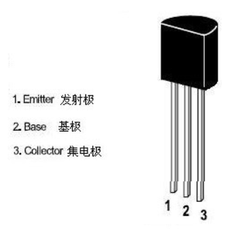
- Polarity judgment: The method for determining the polarity of a transistor is based on the fact that the basic structure of a transistor consists of two back-to-back PN junctions. Utilizing the unidirectional conductivity of PN junctions and the resistance range of a multimeter, we can distinguish the polarity or type of the transistor.
- Determining the base of the transistor: For an NPN transistor, connect the black probe to one electrode and the red probe to the other two electrodes separately. If the measured resistance values are both small, and after swapping the probes, the measured resistance values are both large, it can be concluded that the electrode connected to the black probe during the first measurement is the base. If the measured resistance values are significantly different, the electrode connected to the black probe during the first measurement is not the base, and another electrode should be tested.
- Determining the emitter (e) and collector (c) of the transistor: After determining the base of the transistor, measure the resistance between the emitter and collector by swapping the probes twice. If the results of the two measurements are not equal, the measurement with the smaller resistance value indicates that the red probe is connected to the emitter (e) and the black probe is connected to the collector (c). For a PNP transistor, the method is similar to that for an NPN transistor, except that the roles of the red and black probes are reversed. When measuring the resistance between the emitter and collector, it should be noted that due to the small V(BR)CEO of the transistor, the emitter junction can be easily broken down.
- Determining the type of transistor: If the base of a transistor is known, connect the red probe to the base and the black probe to the other two electrodes separately. If the measured resistance values are both large, the transistor is an NPN type. If the measured resistance values are both small, the transistor is a PNP type.

Hall Sensor
- The A3144 is an integrated S digital output Hall effect non-latching sensor. Bringing a magnet close to the sensor causes the output pin to toggle. This makes the sensor robust and durable. Reed sensors can also work well.
- Working principle: When a beam of charged particles passes through a magnetic field, a force acts on the particles, and the beam deflects from its straight path. The flow of electrons through a conductor is referred to as a beam of charged carriers. When a conductor is placed in a magnetic field perpendicular to the direction of electron flow, they will deflect from their straight path. As a result, one side of the conductor will become negatively charged, while the other side will become positively charged. The voltage between these sides is called the Hall voltage. The separation of the charged particles stops when the force on them from the electric field balances the force from the magnetic field. If the current remains unchanged, the Hall voltage is a measure of the magnetic flux density. Basically, there are two types of Hall effect sensors. One is linear, meaning the output voltage depends linearly on the magnetic flux density; the other is called a threshold type, meaning the output voltage drops sharply at each magnetic flux density level.
- Pin description:
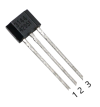
- 1: Power positive (4.5V-24V)
- 2: Power negative
- 3: Signal output

Temperature and Humidity Sensor
- The DHT11 digital temperature and humidity sensor is a composite sensor that contains a calibrated digital signal output, internally controlled by an 8-bit microcontroller with a resistive humidity sensing element and an NTC temperature measuring element.
- The DHT11 sensor uses a single-wire serial interface, and its Dout pin can be directly connected to the I/O port of a microcontroller after being connected to a 5K pull-up resistor. The signal transmission distance can reach over 20 meters, with advantages such as strong anti-interference ability, high cost-effectiveness, and fast response speed. It applies dedicated digital module acquisition technology and temperature and humidity sensing technology to ensure the product has extremely high reliability and excellent long-term stability.
- Pin description:

| GND | Power negative (marked as '-' on the circuit board) |
|---|---|
| VCC | Power positive (input voltage is 3.3V-5V) |
| DATA | Digital output (marked as 'S' on the circuit board) |
| NC | No connection (can be left unconnected) |
74HC595
- The 74HC595 is an 8-bit serial-in, parallel-out shift register with tri-state output: The parallel output is a tri-state output. On the rising edge of SCK, serial data is input from SDL to the internal 8-bit shift register and output from Q7', while the parallel output occurs on the rising edge of LCK, when the data in the 8-bit shift register is stored in the 8-bit parallel output register. When the control signal at the serial data input OE is low (enabled), the output value at the parallel output is equal to the value stored in the parallel output register.
- Pin description
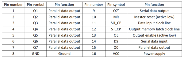
- Q0--Q7: Eight parallel output pins, which can directly control the 8 segments of a digital tube.
- Q7': Cascade output pin. Connect it to the DS pin of the next 595.
- DS: Serial data input pin. For cascading, connect it to Q7' of the previous stage.
- MR: When low, it clears the data in the shift register. Usually connected to VCC to prevent data clearing.
- SH_CP: On the rising edge, the data in the shift register shifts. Q0->Q1->Q2->Q3->...->Q7; on the falling edge, the data in the shift register remains unchanged. (Pulse width: For 5V, a few tens of nanoseconds are sufficient. I usually choose microseconds.)
- ST_CP: On the rising edge, the data in the shift register enters the storage register; on the falling edge, the data in the storage register remains unchanged. I usually keep ST_CP low and generate a positive pulse at the ST_CP pin after the shift is complete (for 5V, a few tens of nanoseconds are sufficient. I usually choose microseconds) to update the display data.
- OE: When high, the output is disabled (high-impedance state). If the microcontroller has enough pins, controlling it with one pin can conveniently produce flashing and extinguishing effects, which saves time and effort compared to controlling it by shifting data through the data pins.

74HC138
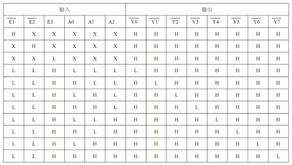
- The 74HC138 is a high-speed CMOS device that is pin-compatible with the low-power Schottky TTL (LSTTL) series. The 74HC138 decoder accepts 3-bit binary weighted address inputs (A0, A1, and A2) and, when enabled, provides 8 mutually exclusive active-low outputs (Y0 to Y7).
- The 74HC138 is a decoder. Decoding is the reverse process of encoding. During encoding, each binary code is assigned a specific meaning, representing a definite signal or object. The process of "translating" the specific meaning of a code state is called decoding, and the circuit that performs the decoding operation is called a decoder.
- Pin description:
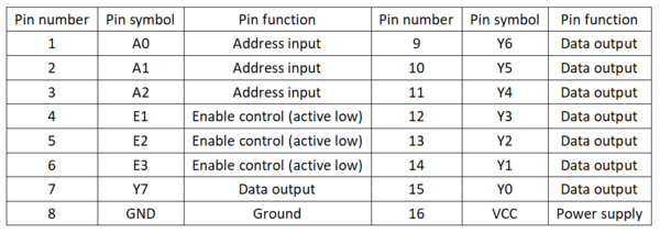
- Truth table:


LM393
- The LM393 is a dual voltage comparator integrated circuit. The output load resistor can be connected to any power supply voltage within the allowable power supply voltage range, without being limited by the voltage value at the Vcc terminal. This output can serve as a simple open-collector SPS (when no load resistor is used). The sink current of the output is limited by the available drive and the beta value of the device. When the maximum current (16mA) is reached, the output transistor will turn off and the output voltage will quickly rise.
- Main features
- Operating temperature range: 0°C to +70°C
- SVHC (Substances of Very High Concern): No SVHC (as of 18-Jun-2010)
- Device designation: 393; Wide operating power supply voltage range, can work with single or dual power supplies; Single power supply: 2 to 36V; Dual power supply: ±1 to ±18V;
- Low quiescent current consumption, ICC = 0.4mA;
- Low input offset voltage, VIO = ±2mV;
- Wide common-mode input voltage range, VIC = 0 to VCC-1.5V;
- Output compatible with TTL, DTL, MOS, CMOS, etc.;
- Output can be connected as an open-collector "OR" gate;
- Surface mount device: Surface mount
- Internal structure:
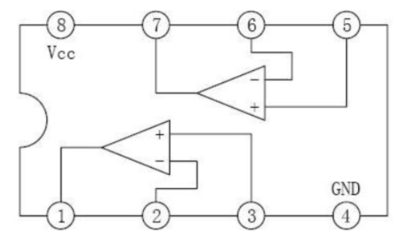

Pin description: 
DC Motor
- The DC motor is the most common type of motor. A DC motor typically has only two leads, a positive and a negative. If these two leads are directly connected to a battery, the motor will rotate. If the leads are switched, the motor will rotate in the opposite direction.
- Do not drive the motor directly from the Arduino board pins. This could damage the circuit board. Use a driver circuit or IC.
4-Digit Common Cathode Seven-Segment Display
- Common cathode seven-segment display: Connect the common terminal COM to ground (GND). When the anode of a segment's LED is at a high level, the corresponding segment lights up. When the anode is at a low level, the segment does not light up.
Driving methods: There are two driving methods for seven-segment displays: static driving and dynamic display.
- Static driving method: Static driving is also known as DC driving. It refers to each segment of the seven-segment display being connected to an 8-bit data line to maintain the displayed character code. These 8-bit data lines can be driven through the I/O ports of a microcontroller or using devices such as BCD-to-decimal converters. Once a character code is sent, the displayed character remains until a new code is sent. The advantage of static driving is simple programming and high display brightness. The disadvantage is that it occupies many I/O ports. When using a microcontroller to control n seven-segment displays, 8n I/O ports are required. Therefore, drivers are often added in practical applications, which increases the complexity of the hardware circuit.
- Dynamic driving method: Dynamic driving means that all the segment select lines of the seven-segment displays are connected in parallel, and the digit select lines control which digit is active. For example, when the microcontroller outputs a character code, all the seven-segment displays receive the same code. Then, the digit select line of the digit to be displayed is activated, and that digit displays the character. The digits that are not selected do not light up. The selected digits are displayed using dynamic scanning. Dynamic scanning means sending the character code and corresponding digit select signals to each digit in turn. Utilizing the afterglow of the LEDs and the persistence of vision of the human eye, as long as the scanning speed is fast enough, it gives the impression that stable characters are displayed, and all selected digits are displaying normally. Compared to static driving, dynamic driving saves a large number of I/O ports and has lower power consumption. However, the brightness of dynamic display is slightly worse than that of static display, so the current-limiting resistors should be slightly smaller than those in a static display circuit.
- Pin description


5V LCD1602
- The 1602 character LCD display module is specifically designed for displaying letters, numbers, symbols, and other dot-matrix LCD display modules. It supports 4-bit and 8-bit data transfer modes. It provides a 5×7 dot matrix + cursor display mode. It includes a display data buffer (DDRAM), a character generator (CGROM), and a character generator (CGRAM). CGRAM can be used to store up to 8 custom 5×8 dot matrix graphic character patterns. It offers a rich set of commands for functions such as clearing the display, returning the cursor to the home position, turning the display on/off, turning the cursor on/off, blinking the displayed characters, shifting the cursor, and shifting the display. It includes an internal power-on auto-reset circuit that automatically initializes the module to its default display operating state when power is applied.
- Pin description:
