USB Relay
From Diustou Wiki
| ||||||||||||||||||||||
| ||||||||||||||||||||||
| ||||||||||||||||||||||
_%E7%A4%BA%E6%84%8F%E5%9B%BE.png)
_%E7%A4%BA%E6%84%8F%E5%9B%BE.png)
_%E7%A4%BA%E6%84%8F%E5%9B%BE.png)
_%E7%A4%BA%E6%84%8F%E5%9B%BE.png)
_%E7%A4%BA%E6%84%8F%E5%9B%BE.png)
Contents
Product Overview
- The USB relay module integrates a high-performance USB-to-serial converter chip and a robust microcontroller. This design enables users to easily control the on/off state of the relays by sending serial commands from a computer via serial port debugging software. The module is ideal for applications requiring reliable and convenient relay control, such as automation systems, laboratory equipment testing, and DIY projects.
Product Specifications
_%E4%BA%A7%E5%93%811.png)
Product Description
USB Relay (TC, 1, Opto)
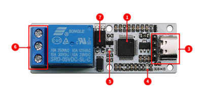
- 1.Microcontroller chip
- 3.Control interface: used for 5V power supply and command control of relays
- 4.Power indicator light
- 5.Relay switch indicator light
- 6.Relay output terminals (NC/COM/NO):
- COM: Common terminal;
- NC: Normally closed terminal, short-circuited to COM before the relay is energized and open after energization;
- NO: Normally open terminal, open before the relay is energized and short-circuited to COM after energization.
- 7.Optocoupler protection circuit
_%E4%BA%A7%E5%93%81%E8%AF%B4%E6%98%8E.png)
USB Relay (TC, 2, Opto)
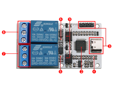
- 2.Microcontroller chip
- 3.Control interface: used for 5V power supply and command control of relays
- 4.Power indicator light
- 5.Indicator light for relay one switch
- 6.Indicator light for relay two switch
- 7.Relay one output terminal (NC1/COM1/NO1):
- COM1: Common terminal;
- NC1: Normally closed terminal, short-circuited to COM1 before the relay is energized and open after energization;
- NO1: Normally open terminal, open before the relay is energized and short-circuited to COM1 after energization.
- 8.Relay two output terminal (NC2/COM2/NO2):
- COM2: Common terminal;
- NC2: Normally closed terminal, short-circuited to COM2 before the relay is energized and open after energization;
- NO2: Normally open terminal, open before the relay is energized and short-circuited to COM2 after energization.
_%E4%BA%A7%E5%93%81%E8%AF%B4%E6%98%8E.png)
USB Relay (TC, 3, Opto)
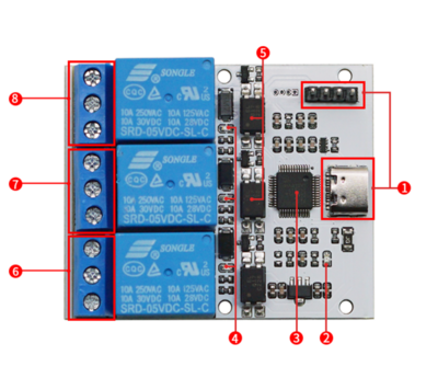
- 1.Control interface: used for 5V power supply and command control of relays
- 2.Power indicator light
- 3.Microcontroller chip
- 4.Relay switch indicator light
- 5.Optocoupler protection circuit
_%E4%BA%A7%E5%93%81%E8%AF%B4%E6%98%8E.png)
- 6.Relay one output terminal (NC1/COM1/NO1):
- COM1: Common terminal;
- NO1: Normally closed terminal, short-circuited to COM1 before the relay is energized and open after energization;
- NC1: Normally open terminal, open before the relay is energized and short-circuited to COM1 after energization.
- 7.Relay two output terminal (NC2/COM2/NO2):
- COM2: Common terminal;
- NO2: Normally closed terminal, short-circuited to COM2 before the relay is energized and open after energization;
- NC2: Normally open terminal, open before the relay is energized and short-circuited to COM2 after energization.
- 8.Relay three output terminal (NC3/COM3/NO3):
- COM3: Common terminal;
- NO3: Normally closed terminal, short-circuited to COM3 before the relay is energized and open after energization;
- NC3: Normally open terminal, open before the relay is energized and short-circuited to COM3 after energization.
USB Relay (TC, 4, Opto)
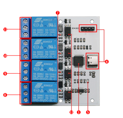
- 1.Microcontroller chip
- 2.Power supply mode selection terminal
- 3.Power Supply Options:
- When using USB power supply, switch the toggle to the USB_P position.
- When using external power supply (via DC jack), switch the toggle to the Ext_P position.
- 4.Control interface: used for 5V power supply and command control of relays
- 5.Power indicator light
- 6.DC power jack: used for external power supply
- 7.Relay switch indicator light
- 8.Relay one output terminal (NC1/COM1/NO1):
- COM1: Common terminal;
- NC1: Normally closed terminal, short-circuited to COM1 before the relay is energized and open after energization;
- NO1: Normally open terminal, open before the relay is energized and short-circuited to COM1 after energization.
- 9.Relay two output terminal (NC2/COM2/NO2):
- COM2: Common terminal;
- NC2: Normally closed terminal, short-circuited to COM2 before the relay is energized and open after energization;
- NO2: Normally open terminal, open before the relay is energized and short-circuited to COM2 after energization.
- 10.Relay three output terminal (NC3/COM3/NO3):
- COM3: Common terminal;
- NC3: Normally closed terminal, short-circuited to COM3 before the relay is energized and open after energization;
- NO3: Normally open terminal, open before the relay is energized and short-circuited to COM3 after energization.
- 11.Relay four output terminal (NC4/COM4/NO4):
- COM4: Common terminal;
- NC4: Normally closed terminal, short-circuited to COM4 before the relay is energized and open after energization;
_%E4%BA%A7%E5%93%81%E8%AF%B4%E6%98%8E.png)
NO4: Normally open terminal, open before the relay is energized and short-circuited to COM4 after energization.
- 12.Optocoupler protection circuit
USB Relay (TC, 8, Opto)
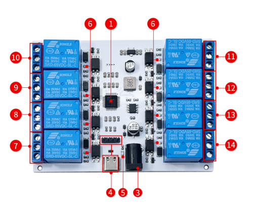
- 1.Microcontroller chip
- 3.DC power jack: used for external power supply.
- The output current of the USB interface is limited, so it is recommended to use external power supply when using multiple relays to ensure stable operation of the circuit.
- 4.Control interface: used for 5V power supply and command control of relays
- 5.Power indicator light
- 6.Relay switch indicator light
- 7.Relay one output terminal (NC1/COM1/NO1):
- COM1: Common terminal;
- NC1: Normally closed terminal, short-circuited to COM1 before the relay is energized and open after energization;
- NO1: Normally open terminal, open before the relay is energized and short-circuited to COM1 after energization.
- 8.Relay two output terminal (NC2/COM2/NO2):
- COM2: Common terminal;
- NC2: Normally closed terminal, short-circuited to COM2 before the relay is energized and open after energization;
- NO2: Normally open terminal, open before the relay is energized and short-circuited to COM2 after energization.
- 9.Relay three output terminal (NC3/COM3/NO3):
- COM3: Common terminal;
- NC3: Normally closed terminal, short-circuited to COM3 before the relay is energized and open after energization;
- NO3: Normally open terminal, open before the relay is energized and short-circuited to COM3 after energization.
- 10.Relay four output terminal (NC4/COM4/NO4):
- COM4: Common terminal;
- NC4: Normally closed terminal, short-circuited to COM4 before the relay is energized and open after energization;
- NO4: Normally open terminal, open before the relay is energized and short-circuited to COM4 after energization.
- 11.Relay five output terminal (NC5/COM5/NO5):
- COM5: Common terminal;
- NC5: Normally closed terminal, short-circuited to COM5 before the relay is energized and open after energization;
- NO5: Normally open terminal, open before the relay is energized and short-circuited to COM5 after energization.
- 12.Relay six output terminal (NC6/COM6/NO6):
- COM6: Common terminal;
- NC6: Normally closed terminal, short-circuited to COM6 before the relay is energized and open after energization;
- NO6: Normally open terminal, open before the relay is energized and short-circuited to COM6 after energization.
- 13.Relay seven output terminal (NC7/COM7/NO7):
- COM7: Common terminal;
- NC7: Normally closed terminal, short-circuited to COM7 before the relay is energized and open after energization;
- NO7: Normally open terminal, open before the relay is energized and short-circuited to COM7 after energization.
- 14.Relay eight output terminal (NC8/COM8/NO8):
- COM8: Common terminal;
- NC8: Normally closed terminal, short-circuited to COM8 before the relay is energized and open after energization;
- NO8: Normally open terminal, open before the relay is energized and short-circuited to COM8 after energization.

User Manual
Communication Protocol for Switch Control
- Data 1 — Start Flag (Default: 0xA0)
- Data 2 — Switch Address Code (0x01 represents the first switch channel)
- Data 3 — Operation Data (0x00 indicates OFF, 0x01 indicates ON)
- Data 4 — Checksum (Calculated as Data1 + Data2 + Data3)
- Note: For USB Relay modules labeled from "USB Relay (TC, 1, Opto)" to "USB Relay (TC, 8, Opto)", the default serial communication baud rate is set to 115200 bps.
Command Instructions
USB Relay (TC, 1, Opto)
- Switch Control Command Instructions (sent in HEX format):
- Open the first USB switch: A0 01 01 A2;
- Close the first USB switch: A0 01 00 A1;
- Open all USB switches: A0 0F 01 B0;
- Close all USB switches: A0 0F 00 AF;
- Query Switch Status (sent in HEX format):
- Status of the first channel: A0 01 02 A3;
- Query all relay statuses: A0 0F 02 B1;
USB Relay (TC, 2, Opto)
- Switch Control Command Instructions (sent in HEX format):
- Open the first USB switch: A0 01 01 A2;
- Close the first USB switch: A0 01 00 A1;
- Open the second USB switch: A0 02 01 A3;
- Close the second USB switch: A0 02 00 A2;
- Open all USB switches: A0 0F 01 B0;
- Close all USB switches: A0 0F 00 AF;
- Query Switch Status (sent in HEX format):
- Status of the first channel: A0 01 02 A3;
- Status of the second channel: A0 02 02 A4;
- Query all relay statuses: A0 0F 02 B1;
USB Relay (TC, 3, Opto)
- Switch Control Command Instructions (sent in HEX format):
- Open the first USB switch: A0 01 01 A2;
- Close the first USB switch: A0 01 00 A1;
- Open the second USB switch: A0 02 01 A3;
- Close the second USB switch: A0 02 00 A2;
- Open the third USB switch: A0 03 01 A4;
- Close the third USB switch: A0 03 00 A3;
- Open all USB switches: A0 0F 01 B0;
- Close all USB switches: A0 0F 00 AF;
- Query Switch Status (sent in HEX format):
- Status of the first channel: A0 01 02 A3;
- Status of the second channel: A0 02 02 A4;
- Status of the third channel: A0 03 02 A5;
- Query all relay statuses: A0 0F 02 B1;
USB Relay (TC, 4, Opto)
- Switch Control Command Instructions (sent in HEX format):
- Open the first USB switch: A0 01 01 A2;
- Close the first USB switch: A0 01 00 A1;
- Open the second USB switch: A0 02 01 A3;
- Close the second USB switch: A0 02 00 A2;
- Open the third USB switch: A0 03 01 A4;
- Close the third USB switch: A0 03 00 A3;
- Open the fourth USB switch: A0 04 01 A5;
- Close the fourth USB switch: A0 04 00 A4;
- Open all USB switches: A0 0F 01 B0;
- Close all USB switches: A0 0F 00 AF;
- Query Switch Status (sent in HEX format):
- Status of the first channel: A0 01 02 A3;
- Status of the second channel: A0 02 02 A4;
- Status of the third channel: A0 03 02 A5;
- Status of the fourth channel: A0 04 02 A6;
- Query all relay statuses: A0 0F 02 B1;
USB Relay (TC, 8, Opto)
- Switch Control Command Instructions (sent in HEX format):
- Open the first USB switch: A0 01 01 A2;
- Close the first USB switch: A0 01 00 A1;
- Open the second USB switch: A0 02 01 A3;
- Close the second USB switch: A0 02 00 A2;
- Open the third USB switch: A0 03 01 A4;
- Close the third USB switch: A0 03 00 A3;
- Open the fourth USB switch: A0 04 01 A5;
- Close the fourth USB switch: A0 04 00 A4;
- Open the fifth USB switch: A0 05 01 A6;
- Close the fifth USB switch: A0 05 00 A5;
- Open the sixth USB switch: A0 06 01 A7;
- Close the sixth USB switch: A0 06 00 A6;
- Open the seventh USB switch: A0 07 01 A8;
- Close the seventh USB switch: A0 07 00 A7;
- Open the eighth USB switch: A0 08 01 A9;
- Close the eighth USB switch: A0 08 00 A8;
- Open all USB switches: A0 0F 01 B0;
- Close all USB switches: A0 0F 00 AF;
- Query Switch Status (sent in HEX format):
- Status of the first channel: A0 01 02 A3;
- Status of the second channel: A0 02 02 A4;
- Status of the third channel: A0 03 02 A5;
- Status of the fourth channel: A0 04 02 A6;
- Query all relay statuses: A0 0F 02 B1;
Usage Instructions
Relay Control
- Connect the USB relay module to your computer and install the driver for the CH340 USB-to-serial chip.
- Open serial port debugging software such as STC-ISP or SSCOM32, select a baud rate of 9600, and send commands in hexadecimal (hex) format to control the relays. For example, sending `A0 01 01 A2` will turn on the relay, while sending `A0 01 00 A1` will turn it off. You can choose between manual and automatic sending methods. The following examples are based on the SSCOM32 serial port debugging software:
- Manual Sending:
- Set Parameters: Choose a baud rate of 115200 and check the "Hex Send" option.
- Send Commands:
- Enter the command `A0 01 01 A2` to turn on the relay.
- Enter the command `A0 01 00 A1` to turn off the relay.
- Execute: After entering the command, click "Send" to manually open or close the relay.

- Automatic Sending:
- Set Parameters: Again, choose a baud rate of 115200, click on "Extend" in the SSCOM32 interface, input the commands `A0 01 01 A2` and `A0 01 00 A1`, and check the "Hex Send" option.
- Configure Automatic Loop**: Input the interval time for automatic loop sending and check the "Automatic Loop Send" option to automatically cycle through opening and closing the relay.

Querying Relay Status
- For a three-channel relay module, assuming channels 1 and 2 are open while others are closed, querying the status of each channel will return the following responses:
Query Channel 1
 Send (Hex): A0 01 02 A3
 Receive (ASCII): CH1:ON
 Receive (Hex): 43 48 31 3A 4F 4E 0D 0A
Query Channel 2
 Send (Hex): A0 02 02 A4
 Receive (ASCII): CH2:ON
 Receive (Hex): 43 48 32 3A 4F 4E 0D 0A
Query Channel 3
 Send (Hex): A0 03 02 A5
 Receive (ASCII): CH3:OFF
 Receive (Hex): 43 48 33 3A 4F 46 46 0D 0A
Query All Relays
Send (Hex): A0 0F 02 B1
Receive (ASCII):
CH1:ON
 CH2:ON
 CH3:OFF
Receive (Hex): 43 48 31 3A 4F 4E 0D 0A 43 48 32 3A 4F 4E 0D 0A 43 48 33 3A 4F 46 46 0D 0A


Software
- sscom32
- CH340/CH341 Diver(Supports 32/64-bit Windows 11/10/8.1/8/7/Vista/XP.)