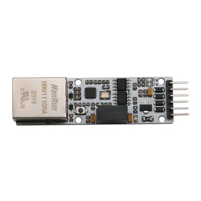
| TTL ETH PLUS
|
|
|
|
|
|
Information
|
|
|
|
Categories: TTL
ETH
|
|
Brand: Diustou
|
|
|
|
|
|
Product Features
- Utilizes the original CH9120 chip, which internally incorporates the Ethernet Media Access Control (MAC) layer and Physical (PHY) layer.
- Enables bidirectional transparent transmission of serial port data and RJ45 Ethernet port data.
- Supports 10M, full-duplex/half-duplex adaptive Ethernet interface, compatible with the 802.3 protocol.
- Supports MDI/MDIX automatic line conversion, allowing for arbitrary connection of crossover or straight-through cables with automatic switching.
- Supports DHCP for automatic IP address acquisition and DNS domain name access.
- Allows configuration of chip working mode, ports, IP, and other network parameters through host computer software or serial port commands.
- Supports four working modes: TCP CLIENT, TCP SERVER, UDP CLIENT, and UDP SERVER.
- Supports the KEEPALIVE mechanism.
- Supports serial port baud rates ranging from 300bps to 921600bps.
- Serial communication level: 5V
- Equipped with on-board TVS (Transient Voltage Suppressor) to effectively suppress surge voltages and transient spike voltages in the circuit, protecting downstream circuits and equipment.
- Equipped with on-board self-resetting fuses to ensure stable output of current and voltage, prevent overcurrent, overvoltage, and electrostatic discharge, with strong impact resistance.
- Equipped with on-board digital isolators, featuring excellent performance characteristics and reliability for signal isolation, resulting in more stable signal transmission.
- Equipped with on-board DC/DC power isolation, providing stable isolated voltage and output short-circuit protection, with no additional power supply required for the isolated end.
- Equipped with a factory reset button for hardware restoration of default configurations.
- Equipped with three types of indicator lights:
- Power indicator light (red): Remains on as long as the power supply is connected normally.
- TX transmission indicator light (green): Flashes when data is received via the RJ45 Ethernet port.
- RX reception indicator light (blue): Flashes when data is received via the TTL interface.
Module Description
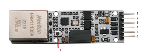
- 1. GND: Ground
- 2. TCPS: In TCP client mode, indicates connection status; low level indicates successful connection.
- 3. CFGO: Serial port configuration mode setting pin; internally pulled up; enters serial port configuration mode when low level is detected, and exits configuration mode when high level.
- 4. RXD: Serial port data receiving end; connects to the TX pin of a TTL device.
- 5. TXD: Serial port data transmitting end; connects to the RX pin of a TTL device.
- 6. 5V: Power supply positive terminal; connects to 5V.
- 7. Hardware factory reset button: Press and hold this button, then power on; release the button after 3 seconds, and the module will reset to factory settings.
Product Selection
User Instructions
Function Introduction
- CH9120 is a network-to-serial transparent transmission chip that enables bidirectional transparent transmission of serial data and network data. It supports four working modes: TCP CLIENT/SERVER and UDP CLIENT/SERVER. The serial port baud rate supports a range of 300bps to 921600bps. Before use, the network and serial port parameters of the chip need to be configured through host computer software. Once configured, CH9120 saves the configuration parameters to its internal storage space. After resetting, CH9120 will operate according to the saved configuration values.
- The basic parameters of CH9120 include: name, MAC address display, automatic IP address acquisition setting, manual IP address setting (including CH9120 IP address, subnet mask, default gateway), and serial port negotiation configuration. The name is mainly for convenient management of CH9120 modules within the local area network, with a length not exceeding 20 bytes. The MAC address field displays the MAC address of the currently selected module. CH9120 has two ways to set network parameters:
- 1) DHCP, which automatically obtains network parameters from a gateway device with DHCP SERVER functionality;
- 2) Manual setting. The serial port negotiation configuration function refers to the ability to enter the serial port configuration mode through serial port handshaking, which is disabled by default.
- The port parameters of CH9120 include: network mode, local port, target IP/domain name, destination port, serial port baud rate/data bits/stop bits/parity bits, network cable disconnection handling, RX packet length, RX packet timeout interval, and network connection operation. Network mode (TCP SERVER/CLIENT, UDP SERVER/CLIENT), destination IP address, and local/destination port are the basic parameters for network communication. The destination IP address can also be accessed using a domain name.
- The serial port baud rate range of the chip is 300bps to 921600bps (the baud rate error of the serial port transmission signal is less than 0.5%, and the allowed baud rate error of the serial port reception signal is not less than 2%). It supports 5, 6, 7, or 8 data bits, as well as 1 or 2 stop bits. It supports odd, even, no parity, space 0, and mark 1 parity modes.
- Network cable disconnection handling refers to whether CH9120 actively closes the connection internally or takes no action when the network cable is disconnected.
- The RX packet length range is 1 to 512. When the serial port of CH9120 receives data of the set length, CH9120 will immediately package the serial port data and send it out through the network. The timeout setting range is 0 to 200, with a timeout unit of approximately 5ms. For example, when the timeout is set to 1, if the data length in the serial port reception buffer does not reach the RX packet length and no new data is received within 5ms, a serial port timeout occurs. After the serial port timeout, CH9120 will send the data received by the serial port out through the network. When the timeout is set to 0, an internal hardware timeout (no new data received for more than 4 data times) mechanism is enabled, which is suitable for scenarios with high real-time requirements and large-scale data transmission and reception.
- The setting for clearing the serial port buffer refers to how to handle data received by the serial port before the network connection is established. It can be cleared (discarded) or retained when a TCP connection is established.
Default Configuration
Product Testing
Note: If you encounter issues with Ethernet port connectivity, please try the following steps:
- Disable the firewall and antivirus software on your computer (usually found in the Control Panel), and also close any security software such as Safe Guard if installed.
- Check the hardware connections for any errors, such as ensuring the Ethernet port is securely connected and the Ethernet cable is functioning properly.
- Verify that the IP address of your computer is on the same subnet as the IP address of the module.
Hardware Preparation
- Dupont wires Several
- Ethernet cable x1
- PC x1
- USB to TTL or serial cable x1
- TTL ETH PLUS x1
Testing Method
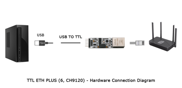
Direct Connection with Computer
- Hardware Connection:
- Connect the RJ45 interface of the TTL ETH PLUS module to the Ethernet port of the computer using an Ethernet cable.
- Connect the TTL interface of the TTL ETH PLUS module to the USB interface of the computer via a USB to TTL module or a serial cable, using four wires (5V to 5V, TXD to RXD, RXD to TXD, GND to GND).
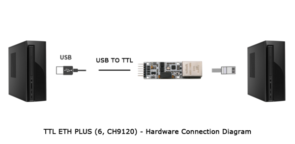
Note: If there is no serial module or serial cable, the module can be powered by a 5V power supply module, and then the TXD and RXD of the module can be shorted together for self-transmission and reception testing.
- Install Driver:
- View Module Configuration:
- Open the Network Configuration Software, click "Search Device", and the searched devices will appear in the upper dialog box. Double-click the searched device, and the configuration information of the corresponding device will appear below and to the right of the software.
- Note: If it doesn't appear, try clicking "Refresh Network Card" and then "Search Device" again. If it still doesn't appear, please check the hardware connection.
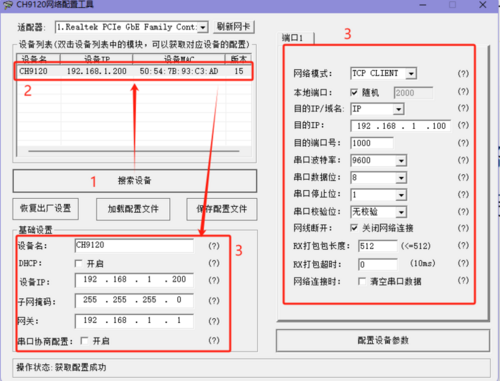
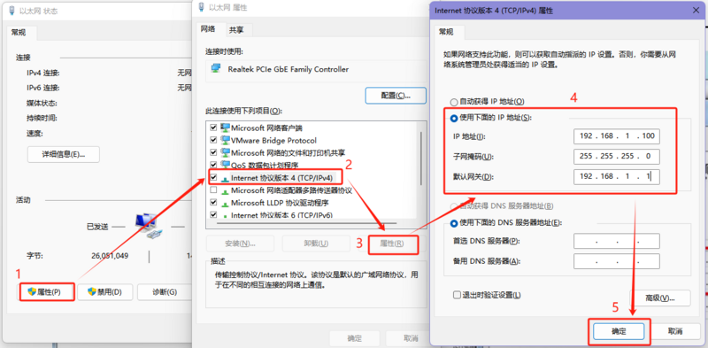
- Modify Computer IP Address:
- Control Panel (File Explorer) -> Network and Internet -> Network and Sharing Center -> Double-click the network adapter -> Properties -> Internet Protocol Version 4 (TCP/IPv4) -> Properties -> Use the IP address below, configure the computer's IP address, subnet mask, and default gateway, then click OK.
- IP Address: Set it to an IP in the same range as the module. Here, use the module's default destination IP of 192.168.1.100.
- Subnet Mask: Use the default setting.
- Default Gateway: Set it according to the IP address.
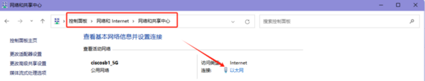
- After setting, you can check if the computer's IP is successfully set by going to Control Panel (File Explorer) -> Network and Internet -> Network and Sharing Center -> Double-click the network adapter -> Details.
- Communication Test:
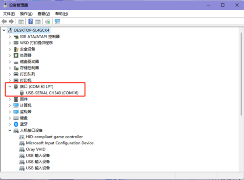
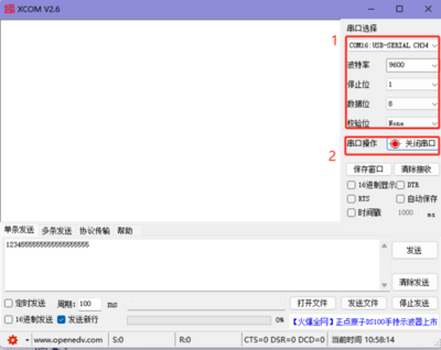
- Open the Serial Port Debugging Assistant, select the corresponding port (viewable through Device Manager), set the serial port baud rate (default for the module is 9600), stop bits (default is 1), data bits (default is 8), and parity (default is None), then open the serial port.
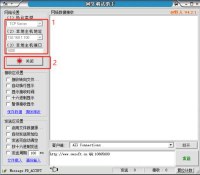
- Open the Network Debugging Assistant, configure the network parameters, click Open to establish a connection.
- Protocol Type: Configure according to the module's working mode. The default working mode of the module here is TCP CLIENT, so the protocol type is set to TCP Server.
- Local Host Address: Set it according to the actual computer IP address. Here, the computer IP is 192.168.1.100.
- Local Host Port: Set it according to the destination port number set when configuring the module. Here, it is the default value of 1000.
- Use the network debugging assistant and serial port debugging assistant to send data respectively, and check if the data is correctly received on the other end.
Connecting to a Router
- Hardware Connection:
- Connect the Ethernet port of the TTL ETH PLUS module and the Ethernet port of the computer to the same router port using Ethernet cables.
- Connect the TTL interface of the TTL ETH PLUS module to the USB interface of the computer via a USB-to-TTL module or a serial cable, using a total of 4 wires (5V to 5V, TXD to RXD, RXD to TXD, GND to GND).
Note: If there is no serial module or cable, you can perform a self-transmission test by shorting the TXD and RXD pins together after powering the module with a 5V power supply.
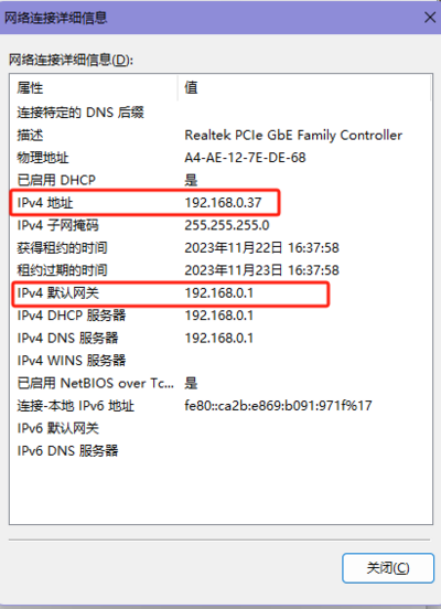
- Checking the Computer's IP Address:
- Control Panel (File Explorer -> Network & Internet -> Network and Sharing Center -> Double-click the network adapter -> Details -> View the computer's IP address (e.g., 192.168.0.37)).
- Installing the Driver:
- Changing Module Configuration:
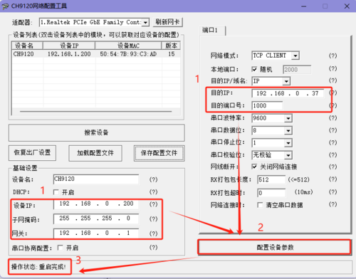
- Open the Network Configuration Software, click "Search Device", and the searched devices will appear in the dialog box above. Double-click the found device, and the configuration information for the corresponding device will appear below and to the right of the software.
- Note: If no devices appear, try clicking "Refresh Network Card" and then "Search Device" again. If still no devices appear, please check the hardware connection.
- Modify the device IP, gateway, destination IP, and destination port number. After making the changes, click "Configure Parameter Settings" and wait for the setup to complete.
- Device IP: Set it to an IP in the same subnet as the computer. If the computer's IP is 192.168.0.37, set the module's IP to 192.168.0.200. Also, ensure that the IP address is not already in use when setting it.
- Gateway: Set the corresponding gateway based on the IP address.
- Destination IP: Set it based on the actual IP address of the connected computer. Here, the computer's IP is 192.168.0.37.
- Destination Port Number: Customize as needed. The default value here is 1000.
- After configuration, click "Search Device" again, double-click the found device, and check if the configuration was successful.
- Communication Test:
- Open the Serial Port Debugging Assistant, select the corresponding port (viewable through Device Manager), set the serial port baud rate (default is 9600), stop bits (default is 1), data bits (default is 8), and parity (default is None), and open the serial port.
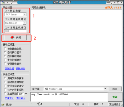
- Open the Network Debugging Assistant, configure the network parameters, click "Open" to establish a connection.
- Protocol Type: Configure according to the module's operating mode. The default operating mode here is TCP CLIENT, so set the protocol type to TCP Server.
- Local Host Address: Set it based on the actual computer's IP address. Here, the computer's IP is 192.168.0.37.
- Local Host Port: Set it based on the destination port number configured when setting up the module. The default here is 1000.
- Use the network debugging assistant and serial port debugging assistant to send data and check if the data is correctly received on the other end.
Mode Description
TCP SERVER
- TCP Server refers to the TCP server. In TCP Server mode, the module listens on a local port, accepts and establishes a connection for data communication when a connection request is received. When data is received on the module's serial port, it simultaneously sends the data to the client device connected to the module. It is commonly used for communication with TCP clients within a local area network. Like TCP Client, it distinguishes between connection and disconnection to ensure reliable data exchange.
- When the module operates as a TCP Server, it first listens on the locally set port, responds to connection requests when they are received, and establishes a connection. After receiving data on the serial port, it sends the data to the device connected to the TTL ETH PLUS Ethernet port. It can accept up to 1 TCP Client connection.
- When the module operates as a TCP Server, it actively listens on the local port number and does not monitor the connected IP and port number. When the number of connections exceeds the maximum, it actively disconnects the oldest connection.
- Application example:
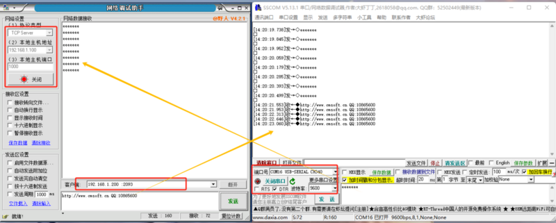
- Set the module's operating mode to TCP Server, with a local port number of 2000 (note: the mention of "local port number as random" here seems redundant since a specific port number is already given; it might be a mistake). Click to configure device parameters, and after setting, search for the device. Once the module is found, check if the set parameters are correct.
- Connect the module's Ethernet port to a network debugging assistant on a PC, set the protocol type to TCP Client, with the PC's IP as 192.168.1.100 and the remote host address as 192.168.1.200 port 2000, and establish a connection.
- Set the correct serial port parameters, click to open the serial port, click to send, and receive bidirectional pass-through data.
TCP CLIENT
- TCP Client refers to the TCP client. It actively initiates a connection to the server for implementing data interaction between the serial port and the server. According to the TCP protocol specifications, TCP Client distinguishes between connection and disconnection, thereby ensuring reliable data exchange. It is commonly used for data interaction between devices and servers and is the most frequently used method for networked communication.
- When the module operates as a TCP Client, it needs to connect to a TCP Server. The parameters that need attention are the destination IP and destination port number. The destination IP is for a device on the same local network.
- When the module acts as a TCP Client, it will actively connect to the target port of the target IP and will not accept other connection requests.
- When the module operates as a TCP Client, the local port number of the TTL ETH PLUS should be set to random. This allows the TTL ETH PLUS to access the server using a random port number, which can resolve issues where the server judges the connection status as abnormal and blocks reconnection requests from the TTL ETH PLUS, leading to reconnection failures.
- Application example:
- Set the module's operating mode to TCP Client, with a destination IP of 192.168.1.100, a remote port number of 1000, and a local port number set to random. Click to configure device parameters, and after setting, search for the device. Once the module is found, check if the set parameters are correct.
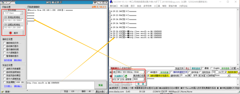
- Connect the module's Ethernet port to a network debugging assistant on a PC, set the protocol type to TCP Server, with the PC's IP as 192.168.1.100 and the listening port number as 1000. The network side of the testing software displays connection information: 192.168.1.200:2093 (randomly assigned port number).
- Set the correct serial port parameters, click to open the serial port, click to send, and receive bidirectional pass-through data.
UDP SERVER
- A UDP Server refers to a system that, based on standard UDP, does not verify the source IP address. Upon receiving a UDP data packet, it changes the destination IP to the source IP and port number. When sending data, it sends to the most recently communicated IP and port number.
- This mode is typically used in scenarios where multiple network devices need to communicate with a module and TCP data transmission is not desired due to speed and frequency requirements.
- Application example:
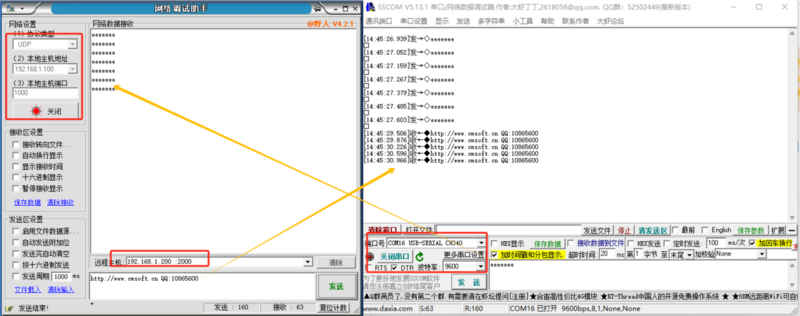
- Set the module's operating mode to UDP Server, with a destination IP of 192.168.1.100, a remote port number of 1000, and a local port number of 2000. Click to configure device parameters, and after setting, search for the device. Once the module is found, check if the set parameters are correct.
- Connect the module's Ethernet port to a network debugging assistant on a PC, set the protocol type to UDP, with the PC's IP as 192.168.1.100 and the listening port number as 1000, and establish a connection.
- Set the correct serial port parameters, click to open the serial port, click to send data via the serial port. When the network debugging assistant receives serial port data, the remote host will change to the module's IP and port. Then click to send data via the network, sending data to the serial port.
UDP CLIENT
- UDP Client is a connectionless transport protocol that provides a simple, unreliable message delivery service for transactions. There is no establishment or disconnection of connections; data can be sent to the other party simply by specifying the IP and port. It is typically used in data transmission scenarios where packet loss rate is not a concern, data packets are small, transmission frequency is high, and data needs to be sent to a specified IP.
- In UDP Client mode, the module will only communicate with the target IP and target port number. If data does not come from this channel, it will not be received by the TTL ETH PLUS.
- Application example:
- Set the module's operating mode to UDP Client, with a destination IP of 192.168.1.100, a remote port number of 1000, and a local port number of 2000. Click to configure device parameters, and after setting, search for the device. Once the module is found, check if the set parameters are correct.
- Connect the module's Ethernet port to a network debugging assistant on a PC, set the protocol type to UDP, with the PC's IP as 192.168.1.100 and the listening port number as 1000, and establish a connection.
- Set the correct serial port parameters, click to open the serial port, click to send data via the serial port. When the network debugging assistant receives serial port data, the remote host will change to the module's IP and port. Then click to send data via the network, sending data to the serial port.
Software
Data Manuals
FAQ

|
Contact Diustou
Our working hours are: 09:00-18:00 (UTC+8 Monday to Saturday)
|
|


 或
或 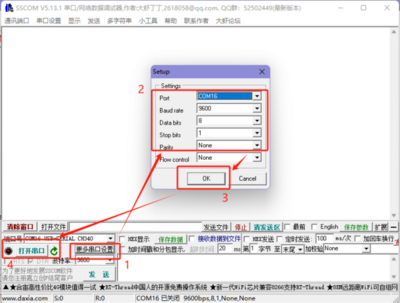 ,
,


