Audio Relay
From Diustou Wiki
Revision as of 18:13, 21 January 2025 by Yousimaier17 (talk | contribs) (→Default Control Commands)
| ||||||||||||||||||||||
| ||||||||||||||||||||||
| ||||||||||||||||||||||


Contents
Product Parameters
- Main Control Chip: US516P6
- Power Supply Interface: Type-C interface or 5.08mm screw terminal block
- Power Supply Voltage:
- Type-C Interface: 5V
- 5.08mm Screw Terminal Block: 5-32V
- Serial Port Chip: CH340
- Serial Port Baud Rate: 115200 (default)
- LED Indicators: Power indicator and relay status indicator
- Output Type: Relay common terminal, normally open terminal, normally closed terminal
- Load Parameters: Capable of handling loads up to 10A/30VDC, 10A/250VAC
- Operating Temperature: -20℃ to 70℃
Product Description
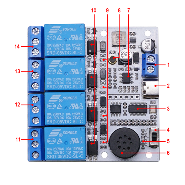
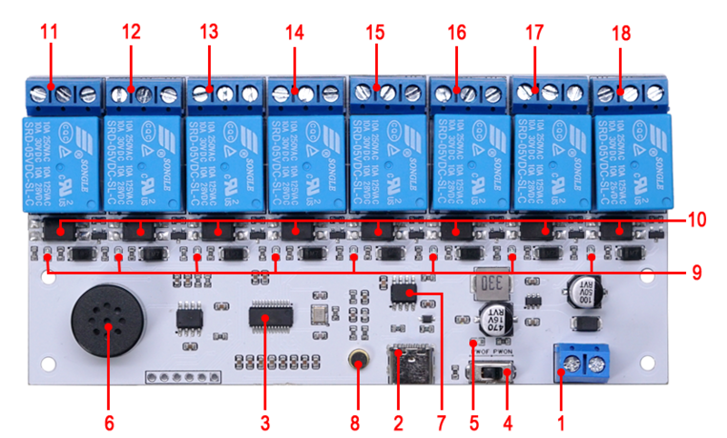
- 1. DC5-32V 5.08mm Power Input Terminal: Supply Voltage
- 2. Type-C Interface: Can be used for 5V power supply and firmware programming
- 3. Audio Chip: US516P6
- 4. Programming Switch
- 5. Power Indicator Light
- 6. Onboard Speaker
- 7. CH340 Serial Communication Chip
- 8. Microphone
- 9. Relay Indicator Light
- 10. Optocoupler Protection Circuit
- 11. Relay One Output Terminal (NC1/COM1/NO1):
- COM1: Common Terminal;
- NC1: Normally Closed Terminal, short-circuited to COM1 before relay activation, open after activation;
- NO1: Normally Open Terminal, open before relay activation, short-circuited to COM1 after activation.
- 12. Relay Two Output Terminal (NC2/COM2/NO2):
- COM2: Common Terminal;
- NC2: Normally Closed Terminal, short-circuited to COM2 before relay activation, open after activation;
- NO2: Normally Open Terminal, open before relay activation, short-circuited to COM2 after activation.
- 13. Relay Three Output Terminal (NC3/COM3/NO3):
- COM3: Common Terminal;
- NC3: Normally Closed Terminal, short-circuited to COM3 before relay activation, open after activation;
- NO3: Normally Open Terminal, open before relay activation, short-circuited to COM3 after activation.
- 14. Relay Four Output Terminal (NC4/COM4/NO4):
- COM4: Common Terminal;
- NC4: Normally Closed Terminal, short-circuited to COM4 before relay activation, open after activation;
- NO4: Normally Open Terminal, open before relay activation, short-circuited to COM4 after activation.
- 15. Relay Five Output Terminal (NC5/COM5/NO5):
- COM5: Common Terminal;
- NC5: Normally Closed Terminal, short-circuited to COM5 before relay activation, open after activation;
- NO5: Normally Open Terminal, open before relay activation, short-circuited to COM5 after activation.
- 16. Relay Six Output Terminal (NC6/COM6/NO6):
- COM6: Common Terminal;
- NC6: Normally Closed Terminal, short-circuited to COM6 before relay activation, open after activation;
- NO6: Normally Open Terminal, open before relay activation, short-circuited to COM6 after activation.
- 17. Relay Seven Output Terminal (NC7/COM7/NO7):
- COM7: Common Terminal;
- NC7: Normally Closed Terminal, short-circuited to COM7 before relay activation, open after activation;
- NO7: Normally Open Terminal, open before relay activation, short-circuited to COM7 after activation.
- 18. Relay Eight Output Terminal (NC8/COM8/NO8):
- COM8: Common Terminal;
- NC8: Normally Closed Terminal, short-circuited to COM8 before relay activation, open after activation;
- NO8: Normally Open Terminal, open before relay activation, short-circuited to COM8 after activation.


User Instructions
Default Control Commands
- The speech recognition module comes with the Factory Firmware pre-installed. Please refer to the table below for the default commands:
Audio Relay (4, Opto)

Audio Relay (8, Opto)

Updating Firmware via Serial Port
- Connect the module to a PC using a Type C cable, and install the CH340/CH341 Driver. After successful installation, open Device Manager to check the port number corresponding to the module.
- Open the Firmware Burning Software.
- Select the firmware: C:\Users\yousi\Desktop\jx_firm\jx_su_03t_release_update.bin
- Click the "Burn" button.
- Toggle the DIP switch on the board from POWER OFF to POWER ON to start the download. If it doesn't work, repeat the process by toggling the switch from POWER ON to POWER OFF and then to POWER ON again.
- Wait for the firmware download to complete.


Firmware Creation
- Open the official website, click on "Login/Register" in the top right corner.
- Click on "Product Management" -> "All Products" -> "Import Product".
- Select the "语音识别_配合丢石头USB继电器使用_20240825001.json" file from the default firmware folder.
- Click on "View Details".
- Click on "View" or "Inherit". ("View" allows modifications based on the existing project; "Inherit" creates a copy for modifications. If the current project has been published, click "Inherit" to save modifications.)
- Enter the project interface and make modifications according to your needs. After completing the modifications, click "Save".
- After saving, click "Back" in the top left corner. For the modified project, click "More" -> "Generate SDK" and wait for the SDK to be successfully generated.


参考资料
- CH340/CH341 USB to Serial Windows Driver(Supports 32/64-bit Windows 11/10/8.1/8/7/Vista/XP.)
- US516P6 Chip Manual
- SU-03T Module Related Materials
- Default Commands
- Factory Firmware
- Firmware Burning Software