| GPIO Relay PRO
|
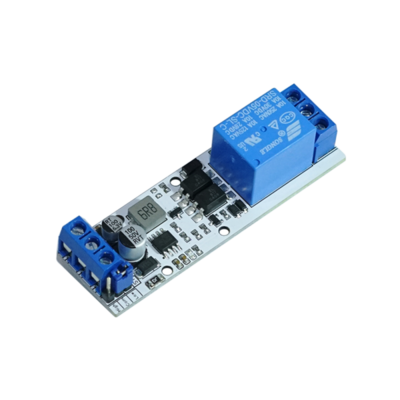
GPIO Relay (1, Adjustable, Opto)
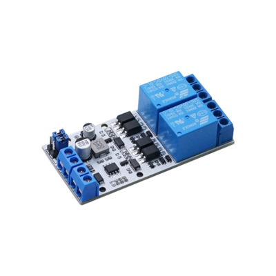
GPIO Relay (2, Adjustable, Opto)
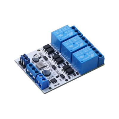
GPIO Relay (3, Adjustable, Opto)
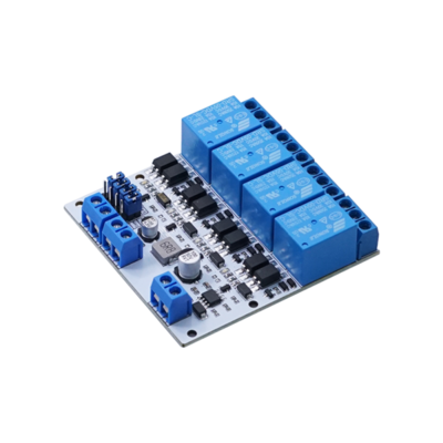
GPIO Relay (4, Adjustable, Opto)
|
|
|
|
|
Information
|
|
|
|
Categories: Relay
|
|
Brand: Diustou
|
|
|
|
|
|
Product Overview
- A relay is an electrical control device that is designed to cause a step change in the controlled quantity within an electrical output circuit when the variation of the input quantity (excitation quantity) meets specified requirements. It establishes an interactive relationship between the control system (also known as the input circuit) and the controlled system (also known as the output circuit). Commonly used in automated control circuits, it essentially functions as an "automatic switch" where a small current controls the operation of a larger current. Therefore, in circuits, relays play roles such as automatic regulation, safety protection, and circuit conversion.
Product Model
Interface Description
Taking the GPIO Relay (4, Adjustable, Opto) as an example:
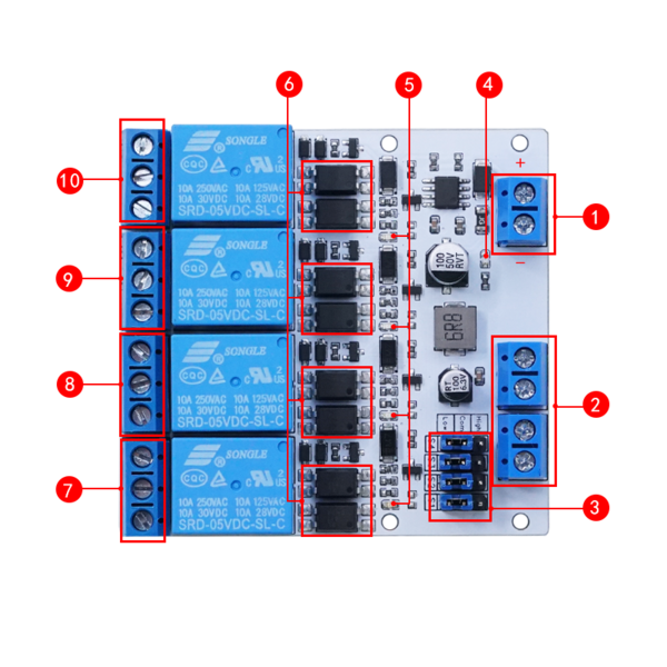
- 1. Power Supply Voltage Input Terminal:
- Accepts a power supply voltage range of 5V-32V.
- 2. Relay Control Terminals: (which can be set to control the relay's operation with either high or low logic levels):
- IN1: Signal trigger terminal for Relay 1
- IN2: Signal trigger terminal for Relay 2
- IN3: Signal trigger terminal for Relay 3
- IN4: Signal trigger terminal for Relay 4
- 3. Relay Trigger Mode Selection Terminal:
- When the jumper cap is connected to LOW, it enables low-level triggering;
- when connected to HIGH, it enables high-level triggering.
- 4. Power Indicator Light
- 5. Relay Switch Indicator Light
- 6. Optocoupler Protection Circuit
- 7. Relay One Output Terminal (NC1/COM/NO1):
- COM1: Common terminal
- NC1: Normally closed terminal, shorted to COM1 before the relay is energized, open after energization
- NO1: Normally open terminal, open before the relay is energized, shorted to COM1 after energization
- 8. Relay Two Output Terminal (NC2/COM/NO2):
- COM2: Common terminal
- NC2: Normally closed terminal, shorted to COM2 before the relay is energized, open after energization
- NO2: Normally open terminal, open before the relay is energized, shorted to COM2 after energization
- 9. Relay Three Output Terminal (NC3/COM/NO3)**:
- COM3: Common terminal
- NC3: Normally closed terminal, shorted to COM3 before the relay is energized, open after energization
- NO3: Normally open terminal, open before the relay is energized, shorted to COM3 after energization
- 10. Relay Four Output Terminal (NC4/COM/NO4)**:
- COM4: Common terminal
- NC4: Normally closed terminal, shorted to COM4 before the relay is energized, open after energization
- NO4: Normally open terminal, open before the relay is energized, shorted to COM4 after energization
Precautions
- Ensure that the power supply and load are used within specified parameters to avoid damage from overuse.
- The rated load and lifespan are reference values that can vary significantly depending on environmental factors, load characteristics, and types. It is recommended to confirm these specifications under actual or simulated real-world conditions.
- The module's load capacity is significantly affected by ambient temperature and its own temperature rise. Adequate air circulation for cooling should be ensured, requiring installation in an environment with good ventilation.
- Electrical durability at high temperatures: When the module is used at high temperatures, its electrical durability will be lower than when used at normal temperatures. Please verify this characteristic during actual use.
FAQ

|
Contact Diustou
Our working hours are: 09:00-18:00 (UTC+8 Monday to Saturday)
|
|
_%E7%A4%BA%E6%84%8F%E5%9B%BE.png)
_%E7%A4%BA%E6%84%8F%E5%9B%BE.png)
_%E7%A4%BA%E6%84%8F%E5%9B%BE.png)
_%E7%A4%BA%E6%84%8F%E5%9B%BE.png)


