| SIngle ToF
|
|
|
|
|
|
|
|
|
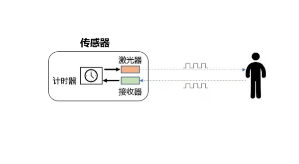
测距原理
- TOF is an abbreviation for Time of Flight, which refers to the time it takes for a signal to travel. Specifically, it involves periodically emitting infrared modulated waves outward. When these waves encounter the target object, they are reflected back and received by the sensor. By measuring the phase difference of the modulated waves' round trip, the flight time can be obtained, allowing the calculation of the relative distance between the sensor and the target object. The schematic diagram is shown below.
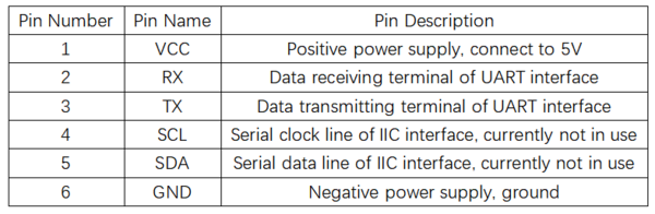
引脚说明
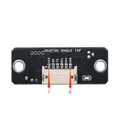
- Shorting the TX and RX pins and then powering on can reset the hardware to factory settings.
产品参数
User Instructions
Demonstration Example
Modbus Protocol
- The single-point TOF laser ranging sensor adopts the industrial standard Modbus protocol. Modbus communication commands are divided into two types: read commands and write commands.
- Read Command (0x03): Read data from the corresponding register.
- Write Command (0x06): Write data to the corresponding register.
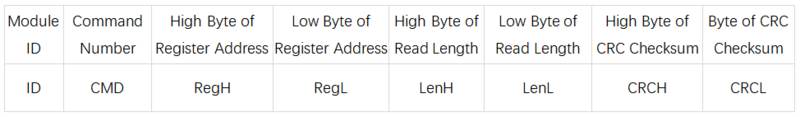
- The specific read and write formats are shown in the following tables:
- Data Frame Sent by the Host Computer
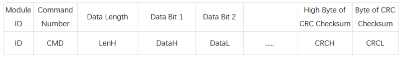
- Module Response Frame
- Example: Reading Measurement Distance
- Send Command: 50 03 00 34 00 01 c8 45
- Received Data: 50 03 02 07 0B 06 7F
- Data Parsing:
- Send: 0x50 is the Modbus ID (default), 0x03 is the command number (read command), 0x34 is the register address (measurement data), 0x01 is the read length (one digit), 0xc8 0x45 are the CRC check digits.
- Receive: 0x50 is the Modbus ID (default), 0x03 is the command number (read command), 0x02 is the data length (two digits), 0x07 0x0B is the measurement data (0x070B corresponds to 1803 in decimal, and the measurement distance is 18036mm), 0x06 0x7F are the CRC check digits.
Modbus Registers
- System Restore
- Register Address: 0x00
- Send Format:
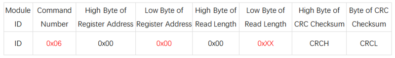
- Description (0xXX):
- Write 0x01 to reset the sensor to factory settings.
- Write 0x02 to restart the sensor.
- Baud Rate Setting
- Register Address: 0x04
- Send Format:
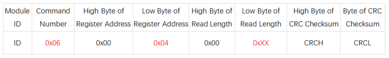
- Description (0xXX):
- Write 0x00 to set the baud rate to 2400.
- Write 0x01 to set the baud rate to 4800.
- Write 0x02 to set the baud rate to 9600.
- Write 0x03 to set the baud rate to 19200.
- Write 0x04 to set the baud rate to 38400.
- Write 0x05 to set the baud rate to 57600.
- Write 0x06 to set the baud rate to 115200 (default).
- Write 0x07 to set the baud rate to 230400.
- Write 0x08 to set the baud rate to 460800.
- Write 0x09 to set the baud rate to 921600.
- Modbus ID Setting
- Register Address: 0x1A
- Send Format:
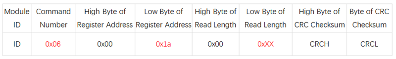
- Description (0xXX):
- Write a value in the range of 0x00~0xFE. The factory default setting is 0x50.
- Measurement Data
- Register Address: 0x34
- Send Format:
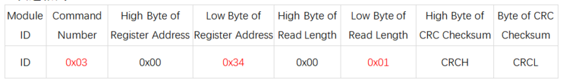
- Description:
- Read the high 8 bits and low 8 bits of the distance data.
- System Mode
- Register Address: 0x38
- Send Format:
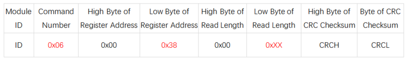
- Description (0xXX):
- Write 0x00 to put the sensor in serial port print mode, where it directly prints strings.
- Write 0x01 to put the sensor in Modbus mode (default).
- Write 0x02 to put the sensor in calibration mode. After calibration is complete, it automatically reverts to Modbus mode.
Host Computer
- Hardware Preparation: Single ToF Module, USB to TTL Module, Computer
- Hardware Connection:
- Usage Steps:
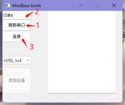
- Connect the Single ToF module to the interface of the USB to TTL module, insert the wired USB to TTL module into the computer's USB port, and open the Host Computer.
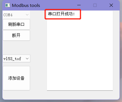
- Click "Refresh Serial Port" in the host software, then select the corresponding port number for the module, and click "Connect" after selecting the port number. At this point, the phrase "Serial Port Opened Successfully" will appear in the dialog box on the right.
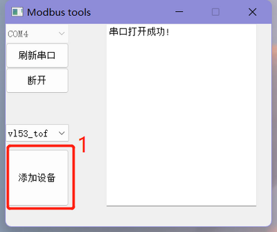
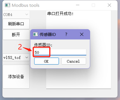
- Click "Add Device" in the bottom left corner, and in the dialog box that appears, enter the module ID (default ID is 0x50), then click "OK".
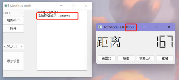
- After successfully setting the ID, a new interface will pop up for viewing the measured distance and configuring the module. At the same time, the phrase "Device Added Successfully ID: 0x50" will appear on the right side of the main interface.
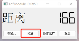
- Calibration:
- Connect the module.
- Place the module 10cm away from a piece of white paper, click the "Calibrate" button to calibrate the module with the corresponding ID.
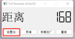
- Set ID:
- Connect the module.
- Click the "Set ID" button, enter a new ID within the range of 01~fe in hexadecimal.
- Restart the module for the changes to take effect. After it takes effect, you need to reconnect the module using the new ID.
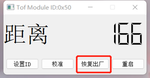
- Factory Reset:
- Connect the module.
- Click the "Factory Reset" button.
- The module will restart for the changes to take effect. After it takes effect, you need to reconnect the module using the default ID (50).
- After a factory reset, the calibration parameters will be cleared, and recalibration is required.
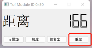
- Restart:
- Connect the module.
- Click the "Restart" button, and the module with the corresponding ID will restart.
Arduino
- Hardware Preparation: Single ToF Module, Arduino
- Hardware Connection:
- Usage Steps:
- Connect the Single ToF module to the Arduino interface, and connect the wired Arduino to the computer.
- Open the code with Arduino IDE and select the corresponding board type and serial port number.
- Modify the IO port number for the serial port where the sensor is connected, based on the actual hardware connection between the sensor and the Arduino.
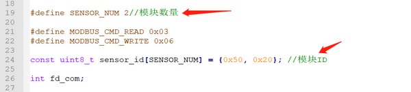
- Modify the number of sensors and sensor IDs according to the actual situation.
- Compile and upload the code.
- Open the Serial Monitor, set the baud rate to 115200, and observe the results.
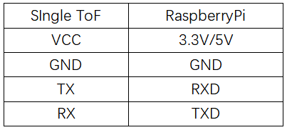
Raspberry Pi
- Hardware Preparation: Single ToF Module, Raspberry Pi
- Hardware Connection:
- Usage Steps
- Burn the Raspberry Pi OS onto an SD card and copy the example code to the system files on the Raspberry Pi.
- Connect the Single ToF module to the Raspberry Pi interface and insert the SD card with the burned OS into the Raspberry Pi.
- Enable the serial port function on the Raspberry Pi.
Execute Command:sudo raspi-config
Select:Interfacing Options
Select:Serial
Select:NO(Would you like a login shell to be accessible over serial?)
Select:YES(Would you like the serial port hardware to be enabled)
Select:YES(The serial login shell is disabled.....)
Restart the Raspberry Pi
- Modify the number of sensors and sensor IDs in the code on the PC according to the actual hardware connection.
- Navigate to the directory where the example code is located and compile it using gcc
sudo gcc vl53_tof.c -o vl53_tof

- Execute the compiled executable file and observe the results
sudo ./vl53_tof
Product Information
FAQ

|
Contact Diustou
Our working hours are: 09:00-18:00 (UTC+8 Monday to Saturday)
|
|


