Difference between revisions of "RS232 TTL"
From Diustou Wiki
Yousimaier17 (talk | contribs) (Created page with "{{Product |images= 400px RS232-TTL (M) ---- 400px RS232-TTL (FM) |categories={{Category|UART}} |brand=DIUSTOU |features=...") |
Yousimaier17 (talk | contribs) |
||
| (One intermediate revision by the same user not shown) | |||
| Line 14: | Line 14: | ||
{{Category|USB Interface}} | {{Category|USB Interface}} | ||
{{Category|UART Interface}} | {{Category|UART Interface}} | ||
| + | |related= | ||
| + | * [[RS232 TTL]] | ||
| + | * [[USB TTL 232 485]] | ||
| + | * [[USB TTL PLUS]] | ||
| + | * [[USB 232 PLUS]] | ||
| + | * [[USB 485 PLUS]] | ||
| + | * [[USB 422 485 PLUS]] | ||
| + | * [[RS232 TTL PLUS]] | ||
| + | * [[TTL 485 PLUS]] | ||
| + | * [[TTL 422 485 PLUS]] | ||
| + | * [[232 485 PLUS]] | ||
| + | * [[232 422 485 PLUS]] | ||
| + | * [[USB TTL PRO]] | ||
| + | * [[USB 232 PRO]] | ||
| + | * [[USB 485 PRO]] | ||
| + | * [[USB 422 485 PRO]] | ||
| + | * [[RS232 TTL PRO]] | ||
| + | * [[TTL 485 PRO]] | ||
| + | * [[TTL 422 485 PRO]] | ||
| + | * [[232 485 PRO]] | ||
| + | * [[232 422 485 PRO]] | ||
| + | * [[USB TTL 422 485 PRO]] | ||
| + | * [[USB TTL 232 422 485 PRO]] | ||
}} | }} | ||
| Line 32: | Line 55: | ||
# Insert the serial port module into the computer, send data through serial port debugging software. If the data can be received, the module functions normally. | # Insert the serial port module into the computer, send data through serial port debugging software. If the data can be received, the module functions normally. | ||
| − | [[File:DB9-PIN.png| | + | [[File:DB9-PIN.png|800px]] |
== Software == | == Software == | ||
Latest revision as of 15:47, 5 February 2025
| ||||||||||||||||||||||
| ||||||||||||||||||||||
| ||||||||||||||||||||||
Product Features
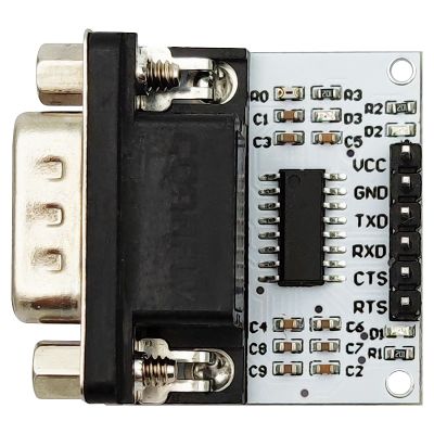
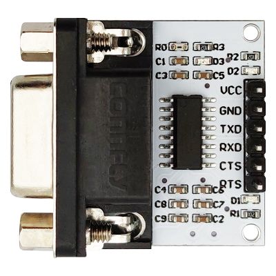
- Main Chip: SP3232
- Interface: DB9, UART
- Output Voltage: 3V-5.5V
- Three indicators:
- PWR LED: Red LED, power indicator
- TXD LED: Green LED, data transmission indicator
- RXD LED: Green LED, data receiving indicator
Test
- An additional serial port module is required.
- Use jumper wires to connect the serial port module and this product (VCC-VCC, GND-GND, TXD-RXD, RXD-TXD)
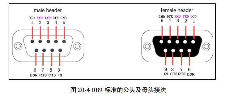
- Connect the TXD and RXD pins of the DB9 connector. (the interface pins of the DB9 female header and male header are defined differently, please refer to the pin notes on the back of the module)
- Insert the serial port module into the computer, send data through serial port debugging software. If the data can be received, the module functions normally.


