Difference between revisions of "USB 232 PLUS"
From Diustou Wiki
Yousimaier17 (talk | contribs) |
Yousimaier17 (talk | contribs) |
||
| (One intermediate revision by the same user not shown) | |||
| Line 13: | Line 13: | ||
|related= | |related= | ||
* [[RS232 TTL]] | * [[RS232 TTL]] | ||
| + | * [[USB TTL 232 485]] | ||
* [[USB TTL PLUS]] | * [[USB TTL PLUS]] | ||
* [[USB 232 PLUS]] | * [[USB 232 PLUS]] | ||
| Line 59: | Line 60: | ||
== Hardware Connection == | == Hardware Connection == | ||
| − | * [[File:USB 232 PLUS_硬件说明.png| | + | * [[File:USB 232 PLUS_硬件说明.png|960px]] |
=== Note === | === Note === | ||
Latest revision as of 17:08, 5 February 2025
| ||||||||||||||||||||||
| ||||||||||||||||||||||
| ||||||||||||||||||||||

Contents
Product Features
- Adopts industrial-grade chips FT232 and SP3232 for high-speed, stable, reliable, and compatible communication.
- Equipped with USB-B interface and DB9 male connector, allowing for smooth and secure plugging and unplugging.
- Features independent power and signal isolation circuits.
- Incorporates an electrostatic ESD protection circuit on the USB side to effectively prevent electrostatic damage and protect downstream circuits and devices.
- The RS232 side RXD, TXD, RTS, and CTS pins are equipped with overcurrent and electrostatic protection circuits.
- Baud rate support range: ≤150K bps
- Onboard five LED indicators for indicating the transmission and reception status of circuit signals.
- PWR light: Green, power indicator
- TXD light: White, RS232 data transmission indicator, data flow: USB->RS232
- RXD light: White, RS232 data reception indicator, data flow: RS232->USB
- RTS light: White, request to send indicator, used to indicate that the device is ready to receive data
- CTS light: White, clear to send indicator, used to determine if data can be sent to the other party
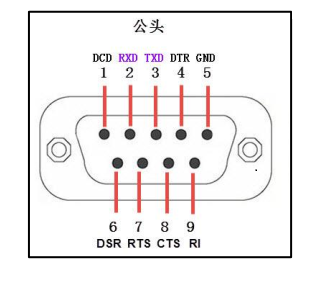
Self-transmission Test
- Short-circuit pins 2 and 3 of the USB 232 PLUS
- TXD (pin 3) - RXD (pin 2)
- For hardware flow control, connect as follows:
- CTS (pin 8) - RTS (pin 7)
- Connect the module to the computer using a USB cable, open the serial port debugging assistant, and select the corresponding port number.
- Send data to the USB 232 PLUS through the serial port debugging assistant and observe if the receiving window of the assistant receives the same data as the sending end.

Hardware Connection

Note
- When using the 232 side for communication, a common ground operation must be performed, i.e., the GND (pin 5) on the 232 side of the module must be connected to the GND of the 232 device.
Driver Installation
1. Download and install the Diver。


2. Verify if the driver is installed successfully. Right-click the Windows logo in the bottom left corner and open "Device Manager".

Expand "Ports (COM & LPT)". If there is a "USB Serial Port" device, the installation is successful.

3. Verify if the module is working properly. Short-circuit the TXD and RXD pins of the module, open theserial port debugging software, , and click "Open Serial Port". Enter any content in the text box, then click the "Send" button. Under normal circumstances, the software will receive and display the same content.

Data Sheet
Resource Download
- FT232 Driver for Windows 7/8/10/11
- Serial Port Debugging Assistant
- PuTTY Serial Port Viewing Software
FAQ
|
