Difference between revisions of "USB TTL 232 485"
From Diustou Wiki
Yousimaier17 (talk | contribs) (Created page with "{{Product |images=400px USB TTL 232 485(CH340) ----- 400px USB TTL 232 485(FT2...") |
Yousimaier17 (talk | contribs) |
||
| (6 intermediate revisions by the same user not shown) | |||
| Line 24: | Line 24: | ||
{{Category|RS232}} | {{Category|RS232}} | ||
{{Category|RS485}} | {{Category|RS485}} | ||
| + | |related= | ||
| + | * [[RS232 TTL]] | ||
| + | * [[USB TTL 232 485]] | ||
| + | * [[USB TTL PLUS]] | ||
| + | * [[USB 232 PLUS]] | ||
| + | * [[USB 485 PLUS]] | ||
| + | * [[USB 422 485 PLUS]] | ||
| + | * [[RS232 TTL PLUS]] | ||
| + | * [[TTL 485 PLUS]] | ||
| + | * [[TTL 422 485 PLUS]] | ||
| + | * [[232 485 PLUS]] | ||
| + | * [[232 422 485 PLUS]] | ||
| + | * [[USB TTL PRO]] | ||
| + | * [[USB 232 PRO]] | ||
| + | * [[USB 485 PRO]] | ||
| + | * [[USB 422 485 PRO]] | ||
| + | * [[RS232 TTL PRO]] | ||
| + | * [[TTL 485 PRO]] | ||
| + | * [[TTL 422 485 PRO]] | ||
| + | * [[232 485 PRO]] | ||
| + | * [[232 422 485 PRO]] | ||
| + | * [[USB TTL 422 485 PRO]] | ||
| + | * [[USB TTL 232 422 485 PRO]] | ||
}} | }} | ||
| Line 58: | Line 81: | ||
Before use, install the corresponding chip driver. | Before use, install the corresponding chip driver. | ||
=== Function Testing === | === Function Testing === | ||
| − | ==== Video Introduction ==== | + | ==== [https://wiki.diustou.com/cn/w/upload/9/9e/USB_TTL_232_485_%E5%8A%9F%E8%83%BD%E6%B5%8B%E8%AF%95.mp4 Video Introduction] ==== |
| − | |||
==== Detailed Instructions ==== | ==== Detailed Instructions ==== | ||
| Line 91: | Line 113: | ||
#Operation Steps: Connect the RS232 interface of module one to the RS232 port of module two with DuPont wires (cross-connect TXD and RXD), and connect the RS485 interface of module two to the RS485 interface of module three (A to A, B to B). Connect the VCC and GND of module two to module one or module three. As shown below, module two serves as the RS232 to RS485 function. Insert modules one and three into the computer, open two serial port debugging assistants, corresponding to the serial port numbers of the two modules. Use one of the serial port debugging assistants to send data and observe if the other serial port debugging assistant receives corresponding data. If so, the RS232 to RS485 function of the module is normal. | #Operation Steps: Connect the RS232 interface of module one to the RS232 port of module two with DuPont wires (cross-connect TXD and RXD), and connect the RS485 interface of module two to the RS485 interface of module three (A to A, B to B). Connect the VCC and GND of module two to module one or module three. As shown below, module two serves as the RS232 to RS485 function. Insert modules one and three into the computer, open two serial port debugging assistants, corresponding to the serial port numbers of the two modules. Use one of the serial port debugging assistants to send data and observe if the other serial port debugging assistant receives corresponding data. If so, the RS232 to RS485 function of the module is normal. | ||
:[[File:USB TTL 232 485_功能测试6.png|800px]] | :[[File:USB TTL 232 485_功能测试6.png|800px]] | ||
| + | |||
=== Wiring Instructions === | === Wiring Instructions === | ||
*'''USB to TTL Mode''' | *'''USB to TTL Mode''' | ||
| − | [[File:USB TTL 232 485_接线1.png| | + | [[File:USB TTL 232 485_接线1.png|960px]] |
*'''USB to RS232 Mode''' | *'''USB to RS232 Mode''' | ||
| − | [[File:USB TTL 232 485_接线2.png| | + | [[File:USB TTL 232 485_接线2.png|960px]] |
*'''USB to RS485 Mode''' | *'''USB to RS485 Mode''' | ||
| − | [[File:USB TTL 232 485_接线3.png| | + | [[File:USB TTL 232 485_接线3.png|960px]] |
*'''TTL to RS232 Mode''' | *'''TTL to RS232 Mode''' | ||
| − | [[File:USB TTL 232 485_接线4.png| | + | [[File:USB TTL 232 485_接线4.png|960px]] |
*'''TTL to RS485 Mode''' | *'''TTL to RS485 Mode''' | ||
| − | [[File:USB TTL 232 485_接线5.png| | + | [[File:USB TTL 232 485_接线5.png|960px]] |
*'''RS232 to RS485 Mode''' | *'''RS232 to RS485 Mode''' | ||
| − | [[File:USB TTL 232 485_接线6.png| | + | [[File:USB TTL 232 485_接线6.png|960px]] |
=== Precautions === | === Precautions === | ||
Latest revision as of 17:09, 5 February 2025
| ||||||||||||||||||||||
| ||||||||||||||||||||||
| ||||||||||||||||||||||
Contents
Product Introduction
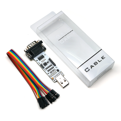
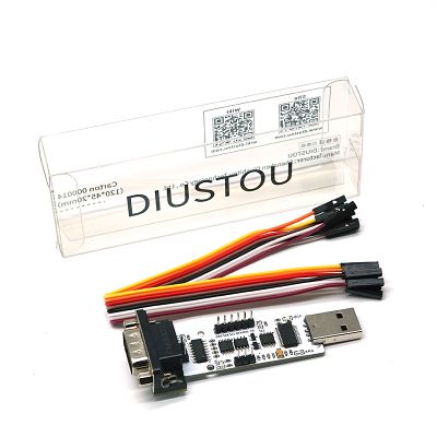
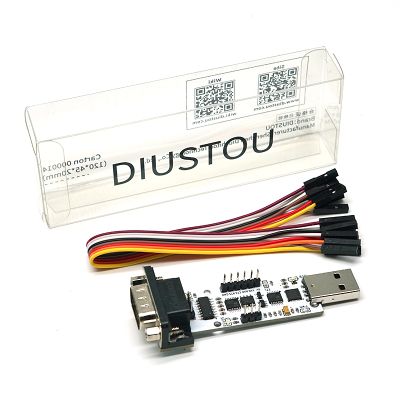
- The USB-to-serial module enables data conversion between a computer's USB interface and a physical serial port. It adds a serial port to computers or other USB hosts that lack one, effectively transforming traditional serial devices into plug-and-play USB devices using the USB-to-serial module.
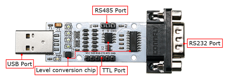
- This module is equipped with three level conversion chips, allowing free conversion among USB, TTL, RS232, and RS485 levels. Its unique circuit design eliminates the need for DIP switch adjustment, enabling immediate use upon wiring. The circuit board measures only 8.3cm x 3.0cm, offering advantages such as small size and easy operation.
Product Description
- Automatic Recovery Fuse: Intelligently prevents burnout with a 500mA automatic recovery fuse. It automatically disconnects when the current exceeds 500mA, protecting your devices and USB ports. Even in the event of a short circuit, it will not cause damage, and the connection can be restored once the circuit is normal.
- LED Indicators: The board features one power indicator and four status indicators to indicate the working status of the module. The status of data transmission can be clearly indicated based on the illumination of the status indicators.
- LED1: Lights up when TTL is transmitting data.
- LED2: Lights up when RS232 is receiving data.
- LED3: Lights up when RS485 is receiving data.
- LED4: Lights up when TTL is receiving data.
Note: Since this module can convert multiple levels simultaneously, multiple indicators may be on or off at the same time during actual use.
- The board is equipped with three level conversion chips, enabling free conversion among USB, TTL, RS232, and RS485 levels without the need for DIP switch control. It allows input from any one port with simultaneous output from the other three ports.
- Baud Rate Range:
- USB TTL 232 485 (CH340)
- Up to 2M baud rate in USB-to-TTL mode.
- Up to 1M baud rate in USB-to-RS232 mode.
- Less than 2M baud rate in USB-to-RS485 mode.
- USB TTL 232 485 (FT232)
- Up to 2M baud rate in USB-to-TTL mode.
- Up to 1M baud rate in USB-to-RS232 mode.
- Up to 2M baud rate in USB-to-RS485 mode.
- USB TTL 232 485 (CP2102)
- Up to 1M baud rate in USB-to-TTL mode.
- Up to 1M baud rate in USB-to-RS232 mode.
- Less than 1M baud rate in USB-to-RS485 mode.
- USB TTL 232 485 (CH340)
User Instructions
Driver Installation
Before use, install the corresponding chip driver.
Function Testing
Video Introduction
Detailed Instructions
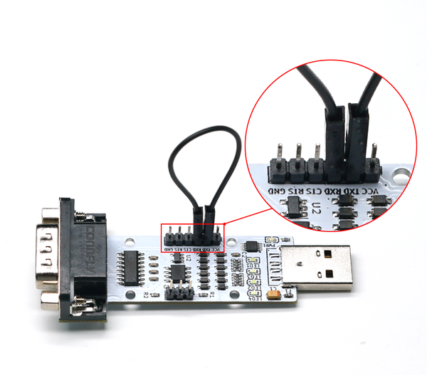
- USB to TTL Self-transmission Test
- Preparation: One module, one DuPont wire or one jumper cap.
- Operation Steps: Connect the TXD and RXD of the module with a DuPont wire (or jumper cap) as shown below. Then insert the module into the computer (the power indicator light is constantly on). Use a serial port debugging assistant to send data and observe if corresponding data is returned (at this time, LED1, LED3, and LED4 will flash). If so, the USB to TTL function of the module is normal.
- USB to RS232 Self-transmission Test
- Preparation: One module, one DuPont wire or one jumper cap.
- Operation Steps: Connect the TXD and RXD of the module with a DuPont wire (or jumper cap) as shown below. Then insert the module into the computer (the power indicator light is constantly on). Use a serial port debugging assistant to send data and observe if corresponding data is returned (at this time, LED1, LED2, LED3, and LED4 will flash). If so, the USB to RS232 function of the module is normal.
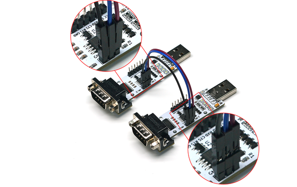
- USB to RS485 Test
- Preparation: Two modules, two DuPont wires.
- Operation Steps: Connect the A and B of the two modules respectively with DuPont wires (A to A, B to B) as shown below. Then insert the two modules into the computer, open two serial port debugging assistants, corresponding to the serial port numbers of the two modules. Use one of the serial port debugging assistants to send data and observe if the other serial port debugging assistant receives corresponding data (at this time, the LED1 of the transmitting module is on, and the LED3 of the receiving module is on). If so, the USB to RS485 function of the module is normal.
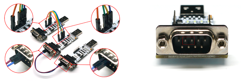
- TTL to RS232 Test
- Preparation: Three modules, several DuPont wires.
- Operation Steps: Connect the TTL interface of module one to the TTL port of module two with DuPont wires (cross-connect TXD and RXD), and connect the RS232 interface of module two to the RS232 interface of module three (cross-connect TXD and RXD). Connect the VCC and GND of module two to module one or module three. As shown below, module two serves as the TTL to RS232 function. Insert modules one and three into the computer, open two serial port debugging assistants, corresponding to the serial port numbers of the two modules. Use one of the serial port debugging assistants to send data and observe if the other serial port debugging assistant receives corresponding data. If so, the TTL to RS232 function of the module is normal.
- TTL to RS485 Test
- Preparation: Three modules, several DuPont wires.
- Operation Steps: Connect the TTL interface of module one to the TTL port of module two with DuPont wires (cross-connect TXD and RXD), and connect the RS485 interface of module two to the RS485 interface of module three (A to A, B to B). Connect the VCC and GND of module two to module one or module three. As shown below, module two serves as the TTL to RS485 function. Insert modules one and three into the computer, open two serial port debugging assistants, corresponding to the serial port numbers of the two modules. Use one of the serial port debugging assistants to send data and observe if the other serial port debugging assistant receives corresponding data. If so, the TTL to RS485 function of the module is normal.
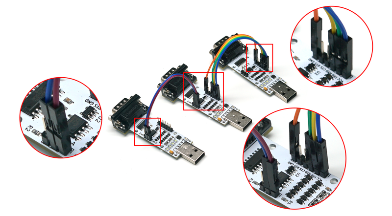
- RS232 to RS485 Test
- Preparation: Three modules, several DuPont wires.
- Operation Steps: Connect the RS232 interface of module one to the RS232 port of module two with DuPont wires (cross-connect TXD and RXD), and connect the RS485 interface of module two to the RS485 interface of module three (A to A, B to B). Connect the VCC and GND of module two to module one or module three. As shown below, module two serves as the RS232 to RS485 function. Insert modules one and three into the computer, open two serial port debugging assistants, corresponding to the serial port numbers of the two modules. Use one of the serial port debugging assistants to send data and observe if the other serial port debugging assistant receives corresponding data. If so, the RS232 to RS485 function of the module is normal.
Wiring Instructions
- USB to TTL Mode
- USB to RS232 Mode
- USB to RS485 Mode
- TTL to RS232 Mode
- TTL to RS485 Mode
- RS232 to RS485 Mode
Precautions
- When this module is used as TTL to RS232 / TTL to RS485 / RS232 to RS485, it needs to be powered. There are two power supply methods: DuPont wire power supply or USB power supply.
- Additionally, regarding common grounding, there are the following situations:
- If the modules connected at both ends of this module are connected to the same device, and this module is connected to the same device via USB, then common grounding is not required among the three modules.
- If the modules connected at both ends of this module are connected to the same device, and this module is powered via a DuPont wire or connected to another device for power supply via USB, then this module only needs to be commonly grounded with one of the modules connected at both ends.
- If the modules connected at both ends of this module are connected to different devices, then common grounding is required among the three modules.
Data Sheets
Resource Download
- CH340/CH341 USB-to-Serial Windows Driver (Supports 32/64-bit Windows 11/10/8.1/8/7/Vista/XP)
- FT232 Driver for Windows 7/8/10/11
- Serial Port Debugging Assistant
- PuTTY Serial Port Viewing Software
- CP2102 Windows Driver (Win7/Win8/Win10)
- CP2102 Windows Universal Driver (Win10 all platforms explanation)
- CP2102 Driver (XP/Win7/Win8)
FAQ
|
