Difference between revisions of "RS232 TTL PRO"
From Diustou Wiki
Yousimaier17 (talk | contribs) |
Yousimaier17 (talk | contribs) |
||
| Line 107: | Line 107: | ||
== Hardware Connection == | == Hardware Connection == | ||
| − | * [[File:RS232 TTL PLUS_硬件连接.png| | + | * [[File:RS232 TTL PLUS_硬件连接.png|960px]] |
* Power must be connected to the TTL side, and the power GND should be connected to the GND of the TTL device and the GND of the TTL side of the module. | * Power must be connected to the TTL side, and the power GND should be connected to the GND of the TTL device and the GND of the TTL side of the module. | ||
* Both the TTL side and the RS232 side must be grounded with the respective devices they communicate with. | * Both the TTL side and the RS232 side must be grounded with the respective devices they communicate with. | ||
Latest revision as of 17:05, 5 February 2025
| ||||||||||||||||||||||
| ||||||||||||||||||||||
| ||||||||||||||||||||||


Contents
Product Features
RS232 TTL PRO (CA)
- Utilizes original SP3232 for stable performance.
- Equipped with a DB9 male connector and 3.5mm screw-type terminal block for smooth and secure plugging and unplugging.
- Operates with a 5V power supply only; TTL signal output level is 5V (same as supply voltage), and input signal level is 5V (compatible with 3.3V signal input).
- Power must be connected to the TTL side during use.
- Uses large-package components for enhanced stability and reliability.
- Features independent power isolation and magnetic coupling isolation circuits.
- TTL side RXD, TXD, RTS, and CTS pins are equipped with overcurrent protection and have strong impact resistance.
- RS232 side RXD, TXD, RTS, and CTS pins are equipped with overcurrent protection and electrostatic protection circuits.
- Note: The electrostatic protection circuit discharges static electricity to the outer metal part of the RS232 plug. For better protection, it is recommended to ground it.
- Supports baud rates up to 150K bps.
- Onboard tri-color LED indicator for indicating circuit power status and signal transmission/reception status.
- Aluminum alloy housing with oxidized matte finish, precise cutouts, sturdy and durable, and exquisite craftsmanship.
RS232 TTL PRO (CB)
- Utilizes original SP3232 chip for high-speed, stable, reliable, and compatible communication.
- Equipped with a DB9 male connector and 5.0mm screw-type terminal block for smooth and secure plugging and unplugging.
- Uses large-package components for enhanced stability and reliability.
- Features independent power isolation and signal isolation circuits.
- TTL side RXD, TXD, RTS, and CTS pins are equipped with overcurrent and electrostatic protection circuits.
- RS232 side RXD, TXD, RTS, and CTS pins are equipped with overcurrent and electrostatic protection circuits.
- Supports baud rates up to 150K bps.
- Onboard five LED indicators for indicating signal transmission/reception status.
- PWR light: Red, power indicator.
- TXD light: Green, RS232 data transmission indicator (data flow: TTL -> RS232).
- RXD light: Blue, RS232 data reception indicator (data flow: RS232 -> TTL).
- RTS light: Yellow, request to send indicator, indicates the device is ready to receive data.
- CTS light: White, clear to send indicator, used to determine if data can be sent to the other party.
- Rail-mounted ABS eco-friendly housing, compact size, easy installation, and cost-effective.
Self-Transmission/Reception Test
TTL Side Self-Transmission/Reception
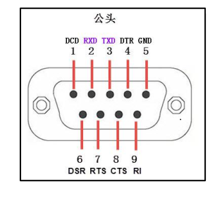
- Connect a USB-to-RS232 serial module to the RS232 port of the RS232 TTL PRO module.
- TXD - RXD (pin 2)
- RXD - TXD (pin 3)
- GND - GND (pin 5)
- For hardware flow control testing, connect as follows:
- CTS - RTS (pin 7)
- RTS - CTS (pin 8)
- Short-circuit the TXD and RXD pins on the TTL side using DuPont wires (or other conductors).
- Connect power to the TTL side of the RS232 TTL PRO module.
- 5V - 5V
- GND - GND
- Connect the serial module to the computer, open the serial port debugging assistant, and select the corresponding port number.
- Send data to the RS232 TTL PRO via the serial port debugging assistant and observe if the receiving window shows the same data as the sending end.

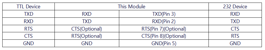
RS232 Side Self-Transmission/Reception
- Connect a USB-to-TTL serial module to the TTL port of the RS232 TTL PRO module.
- TXD - RXD
- RXD - TXD
- GND - GND
- For hardware flow control testing, connect as follows:
- CTS - RTS
- RTS - CTS
- Short-circuit the TXD and RXD pins on the RS232 side using DuPont wires (or other conductors).
- TXD (pin 3) - RXD (pin 2)
- For hardware flow control, connect as follows:
- CTS (pin 8) - RTS (pin 7)
- Connect power to the TTL side of the RS232 TTL PRO module.
- 5V - 5V
- GND - GND
- Connect the serial module to the computer, open the serial port debugging assistant, and select the corresponding port number.
- Send data to the RS232 TTL PRO via the serial port debugging assistant and observe if the receiving window shows the same data as the sending end.
Hardware Connection
- Power must be connected to the TTL side, and the power GND should be connected to the GND of the TTL device and the GND of the TTL side of the module.
- Both the TTL side and the RS232 side must be grounded with the respective devices they communicate with.
- The GND on the TTL side and the GND on the RS232 side are not the same.
