Difference between revisions of "SIngle ToF"
From Diustou Wiki
Yousimaier17 (talk | contribs) (→上位机) |
Yousimaier17 (talk | contribs) (→使用说明) |
||
| Line 28: | Line 28: | ||
*[[File:SIngle ToF_产品参数.png|700px]] | *[[File:SIngle ToF_产品参数.png|700px]] | ||
| − | == | + | == User Instructions == |
| − | === | + | === Demonstration Example === |
[[File:SIngle ToF_演示视频.mp4|800px]] | [[File:SIngle ToF_演示视频.mp4|800px]] | ||
| − | === | + | === Modbus Protocol === |
| − | * | + | *The single-point TOF laser ranging sensor adopts the industrial standard Modbus protocol. Modbus communication commands are divided into two types: read commands and write commands. |
| − | ** | + | **Read Command (0x03): Read data from the corresponding register. |
| − | ** | + | **Write Command (0x06): Write data to the corresponding register. |
| − | * | + | *The specific read and write formats are shown in the following tables: |
| − | ** | + | **Data Frame Sent by the Host Computer |
**[[File:SIngle ToF_发送格式.png|600px]] | **[[File:SIngle ToF_发送格式.png|600px]] | ||
| − | ** | + | **Module Response Frame |
**[[File:SIngle ToF_接收格式.png|600px]] | **[[File:SIngle ToF_接收格式.png|600px]] | ||
| − | ** | + | **Example: Reading Measurement Distance |
| − | *** | + | ***Send Command: 50 03 00 34 00 01 c8 45 |
| − | *** | + | ***Received Data: 50 03 02 07 0B 06 7F |
| − | *** | + | ***Data Parsing: |
| − | **** | + | ****Send: 0x50 is the Modbus ID (default), 0x03 is the command number (read command), 0x34 is the register address (measurement data), 0x01 is the read length (one digit), 0xc8 0x45 are the CRC check digits. |
| − | **** | + | ****Receive: 0x50 is the Modbus ID (default), 0x03 is the command number (read command), 0x02 is the data length (two digits), 0x07 0x0B is the measurement data (0x070B corresponds to 1803 in decimal, and the measurement distance is 18036mm), 0x06 0x7F are the CRC check digits. |
| − | === | + | === Modbus Registers === |
| − | *''' | + | *'''System Restore''' |
| − | ** | + | **Register Address: 0x00 |
| − | ** | + | **Send Format: |
**[[File:SIngle ToF_寄存器1.png|600px]] | **[[File:SIngle ToF_寄存器1.png|600px]] | ||
| − | ** | + | **Description (0xXX): |
| − | *** | + | ***Write 0x01 to reset the sensor to factory settings. |
| − | *** | + | ***Write 0x02 to restart the sensor. |
| − | *''' | + | *'''Baud Rate Setting''' |
| − | ** | + | **Register Address: 0x04 |
| − | ** | + | **Send Format: |
**[[File:SIngle ToF_寄存器2.png|600px]] | **[[File:SIngle ToF_寄存器2.png|600px]] | ||
| − | ** | + | **Description (0xXX): |
| − | *** | + | ***Write 0x00 to set the baud rate to 2400. |
| − | *** | + | ***Write 0x01 to set the baud rate to 4800. |
| − | *** | + | ***Write 0x02 to set the baud rate to 9600. |
| − | *** | + | ***Write 0x03 to set the baud rate to 19200. |
| − | *** | + | ***Write 0x04 to set the baud rate to 38400. |
| − | *** | + | ***Write 0x05 to set the baud rate to 57600. |
| − | *** | + | ***Write 0x06 to set the baud rate to 115200 (default). |
| − | *** | + | ***Write 0x07 to set the baud rate to 230400. |
| − | *** | + | ***Write 0x08 to set the baud rate to 460800. |
| − | *** | + | ***Write 0x09 to set the baud rate to 921600. |
| − | *'''Modbus | + | *'''Modbus ID Setting''' |
| − | ** | + | **Register Address: 0x1A |
| − | ** | + | **Send Format: |
**[[File:SIngle ToF_寄存器3.png|600px]] | **[[File:SIngle ToF_寄存器3.png|600px]] | ||
| − | ** | + | **Description (0xXX): |
| − | *** | + | ***Write a value in the range of 0x00~0xFE. The factory default setting is 0x50. |
| − | *''' | + | *'''Measurement Data''' |
| − | ** | + | **Register Address: 0x34 |
| − | ** | + | **Send Format: |
**[[File:SIngle ToF_寄存器4.png|600px]] | **[[File:SIngle ToF_寄存器4.png|600px]] | ||
| − | ** | + | **Description: |
| − | + | ***Read the high 8 bits and low 8 bits of the distance data. | |
| − | |||
| − | |||
| − | |||
| − | |||
| − | |||
| − | ** | ||
| − | * | ||
| − | |||
| − | |||
| − | |||
| − | |||
| − | |||
| − | |||
| − | |||
| − | |||
| − | |||
| − | |||
| − | |||
| − | |||
| − | |||
| − | |||
| − | |||
| − | |||
| − | |||
| − | |||
| − | |||
| − | |||
| − | |||
| − | |||
| − | |||
| − | |||
| − | |||
| − | |||
| − | |||
| − | |||
| − | |||
| − | |||
| − | |||
| − | |||
| − | |||
| − | |||
| − | |||
| − | |||
| − | |||
| − | |||
| − | |||
| − | |||
| − | |||
| − | |||
| − | |||
| − | |||
| − | |||
| − | |||
| − | |||
| − | |||
| − | |||
| − | |||
| − | |||
| − | |||
| − | |||
| − | |||
| − | |||
| − | |||
| − | |||
| − | |||
| − | |||
| − | |||
| − | |||
| − | |||
| − | |||
| − | |||
| − | |||
| − | |||
| − | |||
| − | |||
| − | |||
| − | |||
| − | |||
| − | |||
| − | |||
| − | |||
| − | |||
| − | |||
| − | |||
== Product Information == | == Product Information == | ||
Revision as of 17:37, 10 January 2025
| ||||||||||||||||||||||
| ||||||||||||||||||||||
| ||||||||||||||||||||||
| ||||||||||||||||||||||

Contents
测距原理
TOF是Time of Flight的缩写,即飞行时间。具体是指通过周期性的向外发出红外光调制波,当调制波遇到被测目标后反射,然后用传感器接收从被测目标反射回来的调制波。通过测量调制波往返的相位差,可得到飞行时间,从而计算出传感器与物体目标之间的相对距离。示意图如下所示。

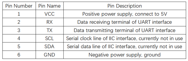
引脚说明
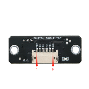
- 短接TX与RX引脚后上电可实现硬件恢复出厂设置


产品参数

User Instructions
Demonstration Example
Modbus Protocol
- The single-point TOF laser ranging sensor adopts the industrial standard Modbus protocol. Modbus communication commands are divided into two types: read commands and write commands.
- Read Command (0x03): Read data from the corresponding register.
- Write Command (0x06): Write data to the corresponding register.
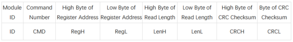
- The specific read and write formats are shown in the following tables:
- Data Frame Sent by the Host Computer
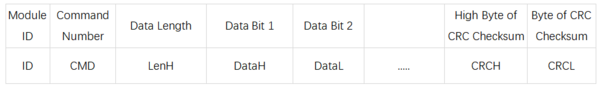
- Module Response Frame
- Example: Reading Measurement Distance
- Send Command: 50 03 00 34 00 01 c8 45
- Received Data: 50 03 02 07 0B 06 7F
- Data Parsing:
- Send: 0x50 is the Modbus ID (default), 0x03 is the command number (read command), 0x34 is the register address (measurement data), 0x01 is the read length (one digit), 0xc8 0x45 are the CRC check digits.
- Receive: 0x50 is the Modbus ID (default), 0x03 is the command number (read command), 0x02 is the data length (two digits), 0x07 0x0B is the measurement data (0x070B corresponds to 1803 in decimal, and the measurement distance is 18036mm), 0x06 0x7F are the CRC check digits.


Modbus Registers
- System Restore
- Register Address: 0x00
- Send Format:
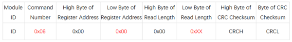
- Description (0xXX):
- Write 0x01 to reset the sensor to factory settings.
- Write 0x02 to restart the sensor.

- Baud Rate Setting
- Register Address: 0x04
- Send Format:
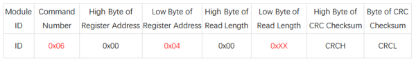
- Description (0xXX):
- Write 0x00 to set the baud rate to 2400.
- Write 0x01 to set the baud rate to 4800.
- Write 0x02 to set the baud rate to 9600.
- Write 0x03 to set the baud rate to 19200.
- Write 0x04 to set the baud rate to 38400.
- Write 0x05 to set the baud rate to 57600.
- Write 0x06 to set the baud rate to 115200 (default).
- Write 0x07 to set the baud rate to 230400.
- Write 0x08 to set the baud rate to 460800.
- Write 0x09 to set the baud rate to 921600.

- Modbus ID Setting
- Register Address: 0x1A
- Send Format:
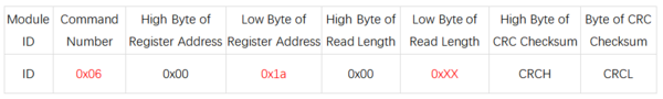
- Description (0xXX):
- Write a value in the range of 0x00~0xFE. The factory default setting is 0x50.

- Measurement Data
- Register Address: 0x34
- Send Format:
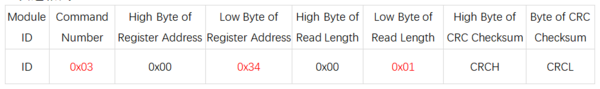
- Description:
- Read the high 8 bits and low 8 bits of the distance data.

Product Information
FAQ
|
