Difference between revisions of "USB 485 PRO"
Yousimaier17 (talk | contribs) |
Yousimaier17 (talk | contribs) |
||
| Line 108: | Line 108: | ||
== Hardware Connection == | == Hardware Connection == | ||
| − | * [[File:USB 485 PLUS_硬件连接.png| | + | * [[File:USB 485 PLUS_硬件连接.png|960px]] |
=== Note === | === Note === | ||
Latest revision as of 17:05, 5 February 2025
| ||||||||||||||||||||||
| ||||||||||||||||||||||
| ||||||||||||||||||||||
Contents
Product Features
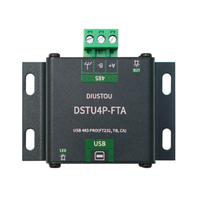
USB 485 PRO (FT232, TB, 1, CA)
- Utilizes industrial-grade chips FT232 and SP3485 for high-speed, stable, reliable, and compatible communication.
- Equipped with a USB-B interface and 5.08mm terminal blocks for smooth and secure connections.
- Employs large-package components for enhanced stability and reliability.
- Features independent power and signal isolation circuits.
- Incorporates an ESD protection circuit on the USB side to effectively prevent electrostatic damage and protect downstream circuits and devices.
- The RS485 side is equipped with overcurrent protection, surge protection, and lightning gas discharge protection circuits.
- The board includes reserved 120R termination resistor pads to enhance signal transmission stability and reduce interference.
- Supports baud rates up to 2Mbps (In practical applications, the baud rate supported by this module is limited by the baud rates supported by the connected devices at both ends and needs to be adjusted according to the actual situation.)
- Onboard two LED indicators for indicating the transmission and reception status of circuit signals.
- USB side indicator: The green light is on when receiving data on the USB side.
- 485 side indicator: The green light is on when receiving data on the 485 side.
- Aluminum alloy housing with oxidized matte finish, precise cutouts, sturdy and durable, and exquisite craftsmanship.
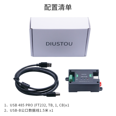
USB 485 PRO (FT232, TB, 1, CB)
- Utilizes industrial-grade chips FT232 and SP3485 for high-speed, stable, reliable, and compatible communication.
- Equipped with a USB-B interface and 5.0mm screw-type terminal blocks for smooth and secure connections.
- Employs large-package components for enhanced stability and reliability.
- Features independent power and signal isolation circuits.
- Incorporates an ESD protection circuit on the USB side to effectively prevent electrostatic damage and protect downstream circuits and devices.
- The RS485 side is equipped with overcurrent protection, surge protection, and lightning gas discharge protection circuits.
- Onboard 120R termination resistor selection DIP switch to enhance signal transmission stability.
- Supports baud rates up to 2Mbps (In practical applications, the baud rate supported by this module is limited by the baud rates supported by the connected devices at both ends and needs to be adjusted according to the actual situation.)
- Onboard three LED indicators for indicating the transmission and reception status of circuit signals.
- PWR indicator (red): Power indicator.
- TXD indicator (green): RS485 data transmission indicator, data flow: USB->RS485.
- RXD indicator (blue): RS485 data reception indicator, data flow: RS485->USB.
- Rail-mounted ABS eco-friendly housing, compact size, easy installation, and cost-effective.
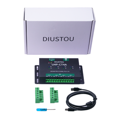
USB 485 PRO (CH344Q, TB, 4, CA)
- Utilizes original CH344Q chip and SP485 for 480Mbps high-speed USB interface communication, reliable, and compatible.
- Equipped with a USB-B interface and 5.08mm terminal blocks for smooth and secure connections.
- Features independent power and signal isolation circuits.
- Incorporates an ESD protection circuit on the USB side to effectively prevent electrostatic damage and protect downstream circuits and devices.
- The RS485 side is equipped with overcurrent protection, surge protection, and lightning gas discharge protection circuits.
- Onboard 120R termination resistor selection DIP switch to enhance signal transmission stability and reduce interference.
- Supports baud rates up to 3Mbps (In practical applications, the baud rate supported by this module is limited by the baud rates supported by the connected devices at both ends and needs to be adjusted according to the actual situation.)
- Onboard four LED indicators for indicating the transmission and reception status of circuit signals.
- Red indicator: Power indicator.
- Yellow indicator: ACT pin indicator, indicates the completion status of USB configuration.
- Green indicator: 4-channel 485 signal transmission indicator, data flow: USB->485.
- Blue indicator: 4-channel 485 signal reception indicator, data flow: 485->USB.
- Aluminum alloy housing with oxidized matte finish, precise cutouts, sturdy and durable, and exquisite craftsmanship.
Testing Method
USB 485 PRO (FT232, TB, 1, CA) and USB 485 PRO (FT232, TB, 1, CB)
- Connect the USB 485 PRO to a USB-to-485 serial module.
- A to A
- B to B
- Connect the USB data cable and the USB-to-485 serial module to the computer, open two serial port assistants, and open the COM ports corresponding to the USB data cable and the serial module respectively.
- Use the two serial port assistants to alternately send data and observe if the other serial port assistant receives the corresponding data.
USB 485 PRO (CH344Q, TB, 4, CA)
- Connect PORT1 to PORT2 and PORT3 to PORT4 of the module.
- A to A
- B to B
- Connect the USB data cable to the computer, open four serial port assistants, and open the COM ports corresponding to the four ports (PORT1~PORT4).
- Use the two serial port assistants connected to the ports to alternately send data and observe if the other serial port assistant receives the corresponding data.
Hardware Connection
Note
- Fully consider the lightning protection design and anti-interference design of the 485 bus. When transmitting over long distances in the field, connecting the module's "ground" terminal to the earth can effectively reduce interference and provide lightning protection, making the 485 bus safer. For short-distance transmission indoors, it is not necessary to connect to the earth.
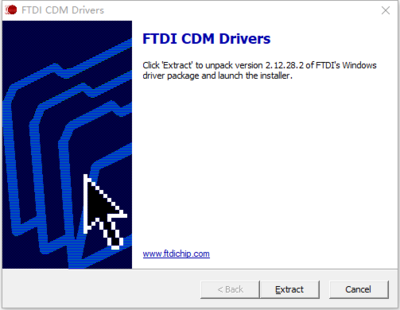
Driver Installation
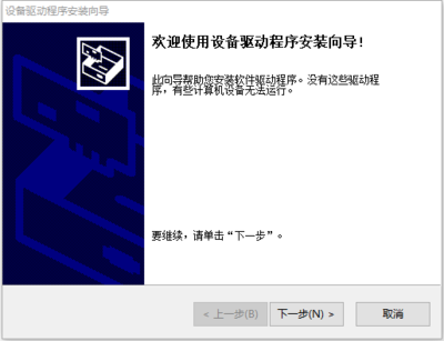
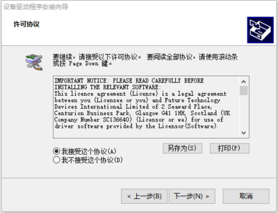
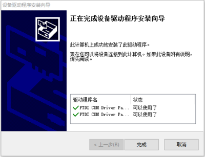
1. Download and install the Diver。
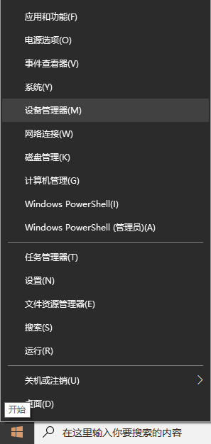
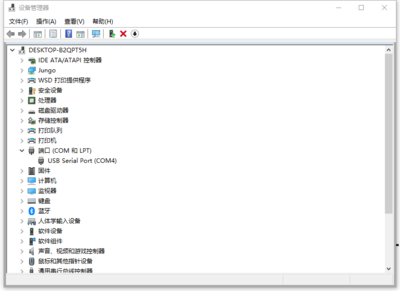
2. Verify if the driver is installed successfully. Right-click the Windows logo in the bottom left corner and open "Device Manager".
Expand "Ports (COM & LPT)". If there is a "USB Serial Port" device, the installation is successful.
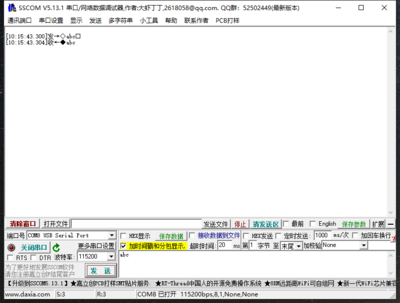
3. Verify if the module is working properly. Short-circuit the TXD and RXD pins of the module, open theserial port debugging software, , and click "Open Serial Port". Enter any content in the text box, then click the "Send" button. Under normal circumstances, the software will receive and display the same content.
Data Sheet
Resource Download
- FT232 Driver for Windows 7/8/10/11
- Serial Port Debugging Assistant
- PuTTY Serial Port Viewing Software
- CH344Q window Driver
- Supports 32/64-bit Windows 11/10/8.1/8/7/Vista/XP/2000, and Server 2022/2019/2016/2012/2008/2003.
- CH344Q macOS Driver
- Supports OS X 10.9 to 10.15, OS X 11 (Big Sur) and above, with installation guide documentation included.
- CH344Q Android Driver
- For Android OS version 4.4 and above, USB Host mode is supported without the need to load Android kernel drivers or require root permissions. It includes an APK installer, library files (Java Driver), and an App Demo routine (USB to UART Demo Project SDK).
FAQ
|
