Difference between revisions of "RS232 Modbus Relay"
Yousimaier17 (talk | contribs) |
Yousimaier17 (talk | contribs) |
||
| Line 96: | Line 96: | ||
=== Introduction to Modbus RTU Commands === | === Introduction to Modbus RTU Commands === | ||
*Modbus devices execute relevant operations by receiving Modbus RTU commands from external control terminals (such as host computers/MCUs). A frame of commands generally consists of the device address, function code, register address, register data, and checksum. The frame length is related to the function code. Typically, the first byte of each frame of data is the device address, with a settable range of 1-255 and a default of 255 (i.e., 0xFF). The last two bytes are the CRC checksum. | *Modbus devices execute relevant operations by receiving Modbus RTU commands from external control terminals (such as host computers/MCUs). A frame of commands generally consists of the device address, function code, register address, register data, and checksum. The frame length is related to the function code. Typically, the first byte of each frame of data is the device address, with a settable range of 1-255 and a default of 255 (i.e., 0xFF). The last two bytes are the CRC checksum. | ||
| − | *Assuming the device address is 255, the commonly used Modbus RTU commands are as follows. For details, please refer to [ | + | *Assuming the device address is 255, the commonly used Modbus RTU commands are as follows. For details, please refer to [https://wiki.diustou.com/cn/%E6%96%87%E4%BB%B6:RS485_Modbus_Relay_%E6%A8%A1%E5%9D%97%E8%AF%B4%E6%98%8E.zip Module User Manual]. |
*'''Turn On Relay 1''' | *'''Turn On Relay 1''' | ||
Latest revision as of 14:31, 22 February 2025
| ||||||||||||||||||||||
| ||||||||||||||||||||||
| ||||||||||||||||||||||
| ||||||||||||||||||||||


Contents
Product Overview
- A relay is an electrical control device that causes a controlled quantity within an electrical output circuit to undergo a predetermined step change when the variation of the input quantity (excitation quantity) meets specified requirements. It establishes an interactive relationship between the control system (also known as the input circuit) and the controlled system (also known as the output circuit). Typically used in automated control circuits, it essentially functions as an "automatic switch" where a small current controls the operation of a larger current. Therefore, in circuits, it plays roles such as automatic regulation, safety protection, and circuit conversion.
- The RS232 Modbus relay module is equipped with a mature and stable 8-bit MCU and an RS232 level communication chip. It adopts the standard MODBUS RTU format for RS232 communication protocol, enabling the detection of 1/2/3/4-channel input signals and the output of 1/2/3/4-channel relays, making it suitable for digital signal detection or power control applications.
Product Features
- Onboard Components: Equipped with a mature and stable 8-bit MCU and an SP3232 level conversion chip.
- Power Supply Voltage: Operates within a range of 5~32V DC.
- Communication Protocol: Supports standard Modbus RTU protocol.
- Communication Interface: Features an RS232 interface.
- Baud Rate: Supports baud rates of 4800, 9600, and 19200 bps; default is 9600 bps. Settings are retained even after power loss.
- Output Signal: Relay switch signal.
- Device Address: Range from 1 to 255; default is 255. The address setting is retained even after power loss.
- Readability: Baud rate, input signal, relay status, and device address can be read using software or commands.
- Relay Configuration: Available in configurations with 2, 3, or 4 relays, each rated for 5V/10A, 250VAC/10A, or 30VDC/10A. Relays can withstand continuous operation up to 100,000 cycles, featuring diode flyback protection and optocoupler isolation circuits for fast response times.
- Indicators: Equipped with relay status indicator lights and power indicator lights.
Product Description
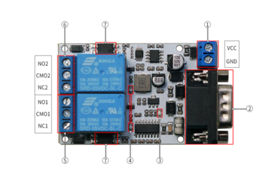
- 1. VCC, GND: DC5-32V 5.08mm power input terminal
- 2.RS232 Communication Interface
- Pin 2: TXD (Transmit Data)
- Pin 3: RXD (Receive Data)
- Pin 5: GND (Ground)
- 3.Power indicator light
- 4.Relay indicator light: Lights up when the relay is engaged
- 5.Relay 1 switching signal output:
- NC1: Normally closed terminal, short-circuited to COM before relay engagement, open after engagement;
- COM1: Common terminal;
- NO1: Normally open terminal, open before relay engagement, short-circuited to COM after engagement.
- 6. Relay 2 switching signal output:
- NC2: Normally closed terminal, short-circuited to COM before relay engagement, open after engagement;
- COM2: Common terminal;
- NO2: Normally open terminal, open before relay engagement, short-circuited to COM after engagement.
- 7. Optocoupler protection circuit

User Instructions
- If the relay cannot be controlled by sending commands, try the following steps
- Insert a clear command: 0d 0a 0d 0a 0d 0a 0d 0a between control commands
- The delay between commands should be greater than 20ms
- The output terminal of the relay is equivalent to an electronic switch and does not output current or voltage itself.
- When the load connected to the relay output terminal has a high power or is an inductive load, it is recommended to add an RC snubber circuit at the load end to reduce the interference on the relay contacts during the switching process.
Host Computer Testing
- Connecting the Serial Port
- Connect the relay module to the USB-to-232 module as follows: Pin 2 (TXD) to TXD; Pin 3 (RXD) to RXD; Pin 5 (GND) to GND.
- Open the Host Computer.
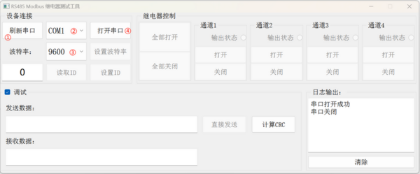
- Refresh the serial port.
- Select the corresponding serial port.
- Select baud rate 9600.
- Open the serial port.

- Setting the Communication ID
- Click the "Read ID" button to automatically read the module's ID and display it in the ID text box (in hexadecimal format). You can also set the module's ID to the value in the ID text box (in hexadecimal format) by clicking the "Set ID" button. The set module ID will be saved in the module and retained even after power-off.
- Click the "Read ID" button to automatically read the module's ID and display it in the ID text box (in hexadecimal format). You can also set the module's ID to the value in the ID text box (in hexadecimal format) by clicking the "Set ID" button. The set module ID will be saved in the module and retained even after power-off.

- Operating the Relay
- You can operate the relay on the corresponding channel or turn all relays on/off simultaneously using the relay control buttons. The output status indicator for the corresponding channel will update accordingly upon receiving a response from the module.
- You can operate the relay on the corresponding channel or turn all relays on/off simultaneously using the relay control buttons. The output status indicator for the corresponding channel will update accordingly upon receiving a response from the module.

- Debugging Function
- The debugging area displays the command data (in hexadecimal format) currently being sent and received by the serial port. Click the "Send Directly" button to send the data in the "Send Data" text box via the serial port. Click the "Calculate CRC" button to automatically calculate the CRC for all data in the "Send Data" text box and append the result to the end, facilitating Modbus command debugging. Note: Since the sent command already includes the CRC, if you manually modify the command to be sent, you need to delete the last two bytes before clicking the "Calculate CRC" button.
- The debugging area displays the command data (in hexadecimal format) currently being sent and received by the serial port. Click the "Send Directly" button to send the data in the "Send Data" text box via the serial port. Click the "Calculate CRC" button to automatically calculate the CRC for all data in the "Send Data" text box and append the result to the end, facilitating Modbus command debugging. Note: Since the sent command already includes the CRC, if you manually modify the command to be sent, you need to delete the last two bytes before clicking the "Calculate CRC" button.

Introduction to Modbus RTU Commands
- Modbus devices execute relevant operations by receiving Modbus RTU commands from external control terminals (such as host computers/MCUs). A frame of commands generally consists of the device address, function code, register address, register data, and checksum. The frame length is related to the function code. Typically, the first byte of each frame of data is the device address, with a settable range of 1-255 and a default of 255 (i.e., 0xFF). The last two bytes are the CRC checksum.
- Assuming the device address is 255, the commonly used Modbus RTU commands are as follows. For details, please refer to Module User Manual.
- Turn On Relay 1
Send: 	FF 05 00 00 FF 00 99 E4
Return: FF 05 00 00 FF 00 99 E4
Note 1: The 3rd and 4th bytes of the sent frame represent the relay address. The addresses for relays 1 to 8 are 0x0000, 0x0001, 0x0002, 0x0003, 0x0004, 0x0005, 0x0006, and 0x0007, respectively.
Note 2: The 5th and 6th bytes of the sent frame represent the data. 0xFF00 represents turning on the relay, and 0x0000 represents turning off the relay.
- Turn Off Relay 1
Send: 	FF 05 00 00 00 00 D8 14
Return: FF 05 00 00 00 00 D8 14
- Turn On All Relays
Send: 	FF 0F 00 00 00 08 01 FF 30 1D
Return: FF 0F 00 00 00 08 41 D3
- Turn Off All Relays
Send:	 FF 0F 00 00 00 08 01 00 70 5D
Return:	 FF 0F 00 00 00 08 41 D3
- Set Device Address to 255
Send: 	00 10 00 00 00 01 02 00 FF EB 80
Return:	00 10 00 00 00 01 02 00 FF EB 80
Note: The 8th and 9th bytes of the sent frame, 0x00FF, represent the device address to be written.
- Read Device Address 255
Send: 	00 03 00 00 00 01 85 DB
Return: 00 03 02 00 FF C5 C4
Note: The 4th and 5th bytes of the response frame, 0x00FF, represent the read device address.
- Set Baud Rate to 9600
Send:	FF 10 03 E9 00 01 02 00 03 8B CC
Return: FF 10 03 E9 00 01 C5 A7
- Read Relay Status
Send: 	FF 01 00 00 00 08 28 12
Return: FF 01 01 01 A1 A0
Generating Checksum
When sending module commands through ready-made host software, the CRC checksum is automatically generated. If you want to test the Modbus relay module using a serial port debugging software (such as SSCOM), you need to manually generate the CRC checksum and append it to the end of the transmission frame. For example, to open the first relay (manual mode):
- The transmission frame for opening/closing the relay (manual mode) consists of: Device address (1Byte) + Function code (1Byte) + Register address (2Byte) + Register data (2Byte) + CRC checksum (2Byte)
- Assuming the device address is 0xFF, the first 6 bytes of the transmission frame would be: FF 05 00 00 FF 00
- Use a CRC checksum tool to calculate the checksum for these 6 bytes: http://www.ip33.com/crc.html

- Swap the high and low bytes of the calculated checksum result E499 to obtain the CRC checksum 99E4, and the complete transmission frame: FF 05 00 00 FF 00 99 E4
- Send this transmission frame to the Modbus relay module through the serial port debugging software SSCOM V5.13.1 to open the first relay (manual mode), as shown below:

References
Precautions
- Please use the power supply and load within the specified parameters and avoid exceeding them.
- The rated load and lifespan are reference values and may vary significantly depending on different environmental factors, load properties, and types. Therefore, it is best to confirm them in actual or simulated actual use.
- The module's load capacity is significantly affected by ambient temperature and its own temperature rise. It needs to be installed in an environment with good air convection for heat dissipation.
- Electrical endurance at high temperatures: When the module is used at high temperatures, its electrical endurance will be lower than at normal temperatures. Therefore, please confirm this in actual use.
FAQ
|

FAQ
|