232 485 PLUS
From Diustou Wiki
Revision as of 11:17, 15 January 2025 by Yousimaier17 (talk | contribs)
| ||||||||||||||||||||||
| ||||||||||||||||||||||
| ||||||||||||||||||||||

Contents
Product Features
- Utilizes original SP3232 and SP3485 chips for high-speed, stable, reliable, and compatible communication.
- The module enables mutual conversion between RS232 and RS485 signals without the need for "receive-transmit" control, making it as simple to use as operating a serial port.
- Equipped with standard DB9 interfaces and 5.08mm plug-and-play terminal blocks for smooth and secure connections.
- The circuit operates on a 5V power supply only.
- Power voltage must be connected to the RS485 end when the module is in use.
- Features independent power and signal isolation circuits.
- The RS232 end is equipped with overcurrent and surge protection functions, ensuring stable current and voltage output and strong impact resistance.
- The RS485 end includes overcurrent protection, surge protection, and lightning gas discharge protection circuits.
- The board has reserved 120R termination resistor pads to enhance signal transmission stability and reduce interference.
- Baud rate support range: up to 2Mbps (In practical applications, the baud rate supported by this module is limited by the baud rates supported by the devices connected at both ends and needs to be adjusted based on actual conditions.)
- Three on-board LED indicator lights for indicating the transmission and reception status of the circuit signals.
- PWR light: green, power indicator
- TXD light: white, RS485 data transmission indicator (data flow: RS232 -> RS485)
- RXD light: white, RS485 data reception indicator (data flow: RS485 -> RS232)
Testing Method
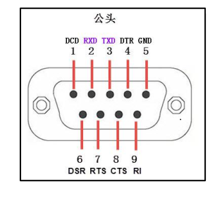
- Connect a USB-to-RS232 serial module to the RS232 port of the 232 485 PLUS module.
- TXD - RXD (pin 2)
- RXD - TXD (pin 3)
- GND - GND (pin 5)
- Connect a USB-to-RS485 serial module to the RS485 port of the 232 485 PLUS module.
- A to A
- B to B
- Connect the power supply to the RS485 end of the 232 485 PLUS module.
- 5V - 5V
- GND - GND
- Connect the USB-to-RS485 serial modules to the computer and open two serial port debugging assistants, selecting the corresponding port numbers.
- Use one of the serial port debugging assistants to send data to the 232 485 PLUS and observe if the receiving window of the other assistant receives the same data as the sending end. If the data is the same, repeat the operation in reverse.

Hardware Connection

Notes
- Power must be connected to the RS485 end when in use.
- This transparent transmission module enables mutual conversion between RS232 and RS485 signals, but RS485 is half-duplex communication. This communication method allows bidirectional communication but not simultaneously in both directions; it must alternate. Even though RS232 is full-duplex communication, it cannot transmit and receive simultaneously; that is, each end of the communication channel can be either a transmitting end or a receiving end, but at the same time, information can only flow in one direction.
- Full consideration has been given to lightning protection and anti-interference design for the RS485 bus. When transmitting over long distances in the field, connecting the module's "ground" terminal to the earth can effectively reduce interference and provide lightning protection, making the RS485 bus safer. For short-distance transmission indoors, grounding is not necessary.
Data Sheet
Resource Download
FAQ
|
