USB TTL 232 422 485 PRO
| ||||||||||||||||||||||
| ||||||||||||||||||||||
| ||||||||||||||||||||||

Contents
Product Introduction
- The USB TTL 232 422 485 PRO is an industrial-grade isolated converter that can realize data conversion between different interfaces such as USB, TTL, RS232, RS422, and RS485. It adopts the original FT232RL and is equipped with power isolation, signal isolation, and TVS protection circuits, housed in an aluminum alloy shell.
- The USB TTL 232 422 485 PRO is easy to operate and supports automatic send/receive conversion. It features fast communication speed, stability, reliability, and safety, making it suitable for various industrial control devices or applications with high communication requirements.
Product Features
- Supports intercommunication between USB-TTL, USB-232, USB-422, USB-485, TTL-232, TTL-422, TTL-485, 232-422, and 232-485 without additional settings.
- Adopts industrial-grade chips FT232RL, SP3485, and SP3232 for high-speed, stable, reliable, and compatible communication.
- The circuit is powered by 5V, and the TTL signal output level is 5V.
- Baud rate support range:
- TTL(UART): ≤2M bps
- RS232: ≤256K bps
- RS422/RS485: ≤1M bps
- Uses USB-B interface and 5.08mm standard terminal blocks for smooth and secure plugging and unplugging.
- Equipped with five LED indicators to show the sending and receiving status of the circuit signals.
- Power indicator: Constantly on when the module is powered on.
- USB indicator: Blinks when data is received on the USB side.
- TTL indicator: Blinks when data is received on the TTL side.
- RS232 indicator: Blinks when data is received on the RS232 side.
- RS485/RS422 indicator: Blinks when data is received on the RS422/RS485 side.
- Circuit features:
- USB side: Includes ESD protection circuit to effectively prevent electrostatic damage and protect downstream circuits and devices.
- TTL side:
- Reserves RTS and CTS pins for serial port flow control.
- Equipped with overcurrent and surge protection functions to ensure stable current and voltage output and strong impact resistance.
- 232 side:
- With RTS input and CTS output functions.
- Equipped with independent power isolation and magnetic coupling isolation circuits.
- Includes overcurrent and surge protection circuits.
- 422/485 side:
- With automatic flow control function.
- Equipped with independent power isolation and magnetic coupling isolation circuits for more stable signal transmission.
- Includes overcurrent protection, surge protection, and lightning gas discharge protection circuits.
- Aluminum alloy shell with oxidized matte finish, precise openings, sturdy and durable, and exquisite craftsmanship.
Product Description

Wiring Instructions
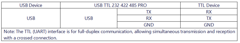
- USB to TTL Mode
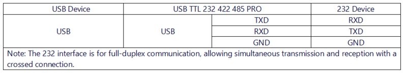
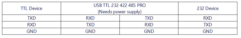
- USB to 232 Mode
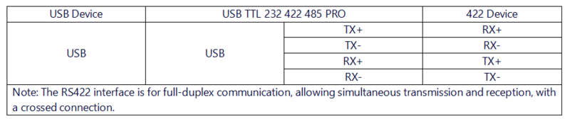
- USB to 422 Mode
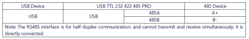
- USB to 485 Mode
- TTL to 232 Mode
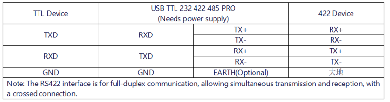
- TTL to 422 Mode
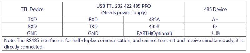
- TTL to 485 Mode
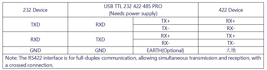
- 232 to 422 Mode
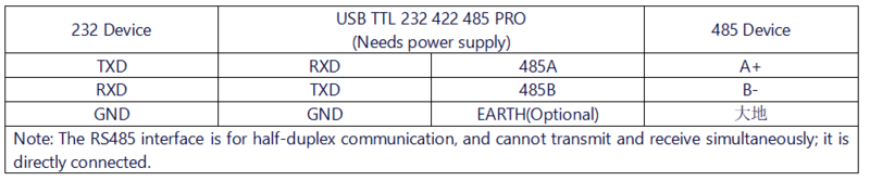
- 232 to 485 Mode


Usage Instructions
Driver Installation
1. Download and install the Diver。


2. Verify if the driver is installed successfully. Right-click the Windows logo in the bottom left corner and open "Device Manager".

Expand "Ports (COM & LPT)". If there is a "USB Serial Port" device, the installation is successful.

3. Verify if the module is working properly. Short-circuit the TXD and RXD pins of the module, open theserial port debugging software, , and click "Open Serial Port". Enter any content in the text box, then click the "Send" button. Under normal circumstances, the software will receive and display the same content.

Testing Instructions
- USB to TTL Mode
Connect the USB TTL 232 422 485 PRO to the target board using Dupont wires, connecting RXD to TXD, TXD to RXD, and GND to GND. Open two serial port debugging assistants on the computer, select the corresponding port numbers, set the same baud rate, click on timed transmission, and it should return normally, as shown in the figure below:

- USB to 232 Mode
Connect the USB TTL 232 422 485 PRO to the target board using Dupont wires, connecting RXD to TXD, TXD to RXD, and GND to GND. Open two serial port debugging assistants on the computer, select the corresponding port numbers, set the same baud rate, click on timed transmission, and it should return normally, as shown in the figure below:

- USB to 485 Mode
Connect the USB TTL 232 422 485 PRO to the target board using Dupont wires, connecting A to A and B to B. Open two serial port debugging assistants on the computer, select the corresponding port numbers, set the same baud rate, click on timed transmission, and it should transmit and receive normally, as shown in the figure below:
- USB to 422 Mode
Connect the USB TTL 232 422 485 PRO to the target board using Dupont wires, connecting RXD+ to TXD+, RXD- to TXD-, TXD+ to RXD+, and TXD- to RXD-. Open two serial port debugging assistants on the computer, select the corresponding port numbers, set the same baud rate, click on timed transmission, and it should transmit and receive normally, as shown in the figure below:

Resource Downloads
- FT232 Driver for Windows 7/8/10/11
- Serial Port Debugging Assistant
- PuTTY Serial Port Viewing Software
- FT232R Data Sheet
FAQ
|
