SIngle ToF
From Diustou Wiki
Revision as of 17:23, 10 January 2025 by Yousimaier17 (talk | contribs) (Created page with "{{Product |images=400px |categories= {{Category|光传感器}} {{Category|传感器}} |brand=丢石头 |features= * 单点TOF激光测距传...")
| ||||||||||||||||||||||
| ||||||||||||||||||||||
| ||||||||||||||||||||||
| ||||||||||||||||||||||

Contents
测距原理
TOF是Time of Flight的缩写,即飞行时间。具体是指通过周期性的向外发出红外光调制波,当调制波遇到被测目标后反射,然后用传感器接收从被测目标反射回来的调制波。通过测量调制波往返的相位差,可得到飞行时间,从而计算出传感器与物体目标之间的相对距离。示意图如下所示。

引脚说明
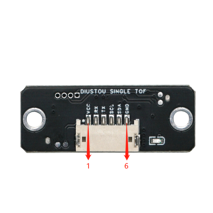
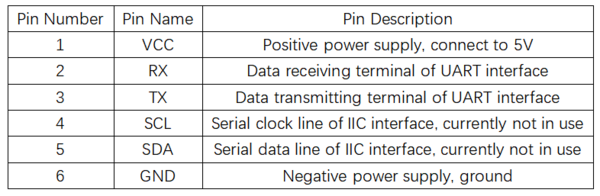
- 短接TX与RX引脚后上电可实现硬件恢复出厂设置


产品参数

使用说明
演示示例
Modbus协议
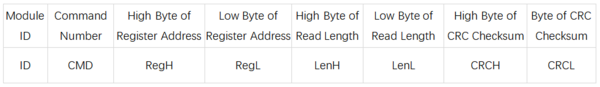
- 单点TOF激光测距传感器采用了工业标准Modbus协议,Modbus通信指令分为两种,读命令与写命令,
- 读命令(0x03):读取相应寄存器数据。
- 写命令(0x06):向相应寄存器写入数据。
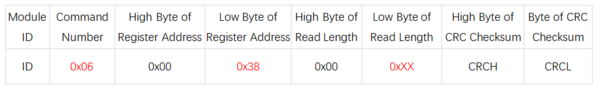
- 具体读写格式如下表:
- 上位机发送数据帧
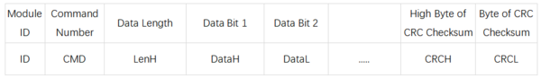
- 模块回复帧
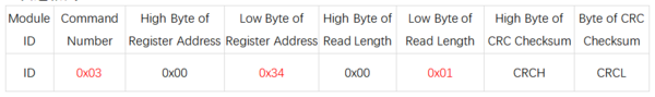
- 示例:读取测量距离
- 发送指令:50 03 00 34 00 01 c8 45
- 接受数据:50 03 02 07 0B 06 7F
- 数据解析:
- 发送:0x50为Modbus ID(默认),0x03为命令号(读命令),0x34为寄存器地址(测量数据),0x01为读取长度(一位),0xc8 0x45为CRC校验位
- 接收:0x50为Modbus ID(默认),0x03为命令号(读命令),0x02为数据长度(两位),0x07 0x0B为测量数据(0x070B对应的十进制为1803,测量距离为18036mm),0x06 0x7F为CRC校验位。


Modbus寄存器
- 系统恢复
- 寄存器地址:0x00
- 发送格式:
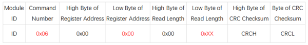
- 说明(0xXX):
- 写入0x01,传感器恢复出厂设置
- 写入0x02,传感器重启

- 波特率设置
- 寄存器地址:0x04
- 发送格式:
- 说明(0xXX):
- 写入0x00,设置波特率为2400
- 写入0x01,设置波特率为4800
- 写入0x02,设置波特率为9600
- 写入0x03,设置波特率为19200
- 写入0x04,设置波特率为38400
- 写入0x05,设置波特率为57600
- 写入0x06,设置波特率为115200(默认)
- 写入0x07,设置波特率为230400
- 写入0x08,设置波特率为460800
- 写入0x09,设置波特率为921600

- Modbus ID设置
- 寄存器地址:0x1A
- 发送格式:
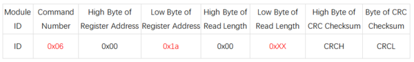
- 说明(0xXX):
- 写入范围为0x00~0xFE,出厂设置默认为0x50

- 测量数据
- 寄存器地址:0x34
- 发送格式:
- 说明:
- 读取数据高8位与距离低8位

- 系统模式
- 寄存器地址:0x38
- 发送格式:
- 说明(0xXX):
- 写入0x00,传感器进入串口打印模式,直接打印字符串。
- 写入0x01,传感器进入Modbus模式(默认)。
- 写入0x02,传感器进入校准模式,校准完成后自动恢复为Modbus模式。

上位机
- 硬件准备:Single ToF模块、USB转TTL模块、电脑
- 硬件连接:
- 使用步骤
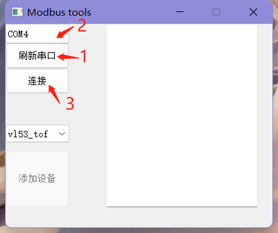
- 将Single ToF接入USB转TTL模块的接口,将接好线的USB转TTL模块插入电脑USB接口,打开上位机软件。
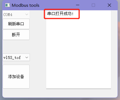
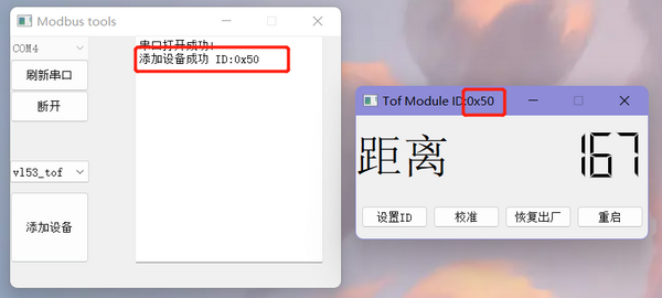
- 点击上位机软件中的 刷新串口 ,然后选择模块对应的端口号,选择好端口号都点击 连接 。此时右侧的对话框内会出现 串口打开成功 字样。
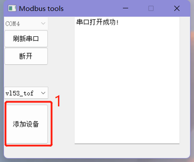
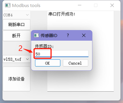
- 点击左下角的 添加设备 ,在出现的对话框内需要输入模块ID(默认ID为0x50),然后点击 OK。
- 设置ID成功后会弹出新的界面出来用来查看测量距离以及对模块进行设置,同时主界面的右侧会出现 添加设备成功 ID:0x50 字样。
- 校准:
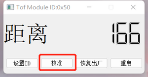
- 连接模组。
- 将模组放在距离白纸10cm的位置,点击 校准 按钮,校准对应ID的模组。
- 设置ID:
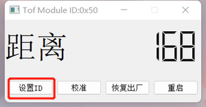
- 连接模组。
- 点击 设置ID 按钮,填入新的ID,范围01~fe,十六进制。
- 重启模组生效,生效后需要用新ID重新连接模组。
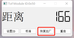
- 恢复出厂:
- 连接模组。
- 点击 恢复出厂 按钮。
- 模组重启生效,生效后需要用默认ID(50)重新连接模组。
- 恢复出厂后会清除校准参数,需重新校准。
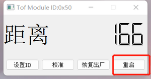
- 重启:
- 连接模组。
- 点击 重启 按钮,对应ID的模组会重启。


Arduino
- 硬件准备:Single ToF模块、Arduino
- 硬件连接:
- 使用步骤:
- 将Single ToF接入Arduino的接口,将接好线的Arduino接入电脑。
- 用Arduino IDE打开代码,并选择对应的板型和串口号。
- 根据实际传感器与arduino的硬件连接修改传感器连接的串口的IO口编号。
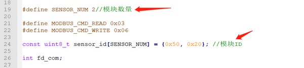
- 根据实际情况修改传感器数量和传感器ID
- 编译和上传
- 打开串口监视器,波特率选择115200,观察结果。


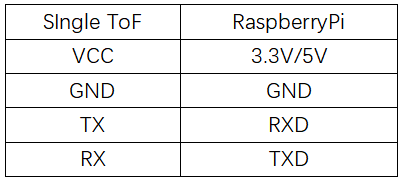
Raspberry Pi
- Hardware Preparation: Single ToF Module, Raspberry Pi
- Hardware Connection:
- Usage Steps
- Burn the Raspberry Pi OS onto an SD card and copy the example code to the system files on the Raspberry Pi.
- Connect the Single ToF module to the Raspberry Pi interface and insert the SD card with the burned OS into the Raspberry Pi.
- Enable the serial port function on the Raspberry Pi.

Execute Command:sudo raspi-config
Select:Interfacing Options
Select:Serial
Select:NO(Would you like a login shell to be accessible over serial?)
Select:YES(Would you like the serial port hardware to be enabled)
Select:YES(The serial login shell is disabled.....)
Restart the Raspberry Pi
- Modify the number of sensors and sensor IDs in the code on the PC according to the actual hardware connection.
- Navigate to the directory where the example code is located and compile it using gcc

sudo gcc vl53_tof.c -o vl53_tof

- Execute the compiled executable file and observe the results

sudo ./vl53_tof

Product Information
FAQ
|
