| SIngle ToF
|
|
|
|
|
|
Information
|
|
|
|
Categories: 光传感器
传感器
|
|
Brand: 丢石头
|
|
|
|
|
|
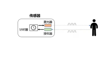
测距原理
TOF是Time of Flight的缩写,即飞行时间。具体是指通过周期性的向外发出红外光调制波,当调制波遇到被测目标后反射,然后用传感器接收从被测目标反射回来的调制波。通过测量调制波往返的相位差,可得到飞行时间,从而计算出传感器与物体目标之间的相对距离。示意图如下所示。
引脚说明
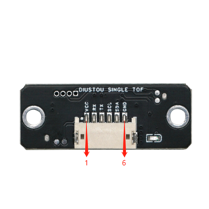
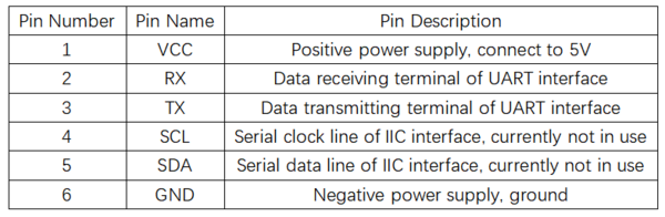
- 短接TX与RX引脚后上电可实现硬件恢复出厂设置
产品参数
使用说明
演示示例
Modbus协议
- 单点TOF激光测距传感器采用了工业标准Modbus协议,Modbus通信指令分为两种,读命令与写命令,
- 读命令(0x03):读取相应寄存器数据。
- 写命令(0x06):向相应寄存器写入数据。
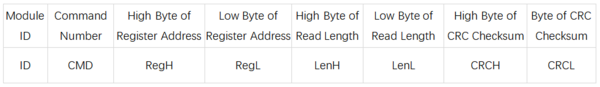
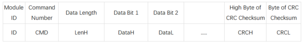
- 具体读写格式如下表:
- 上位机发送数据帧
- 模块回复帧
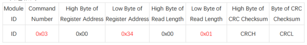
- 示例:读取测量距离
- 发送指令:50 03 00 34 00 01 c8 45
- 接受数据:50 03 02 07 0B 06 7F
- 数据解析:
- 发送:0x50为Modbus ID(默认),0x03为命令号(读命令),0x34为寄存器地址(测量数据),0x01为读取长度(一位),0xc8 0x45为CRC校验位
- 接收:0x50为Modbus ID(默认),0x03为命令号(读命令),0x02为数据长度(两位),0x07 0x0B为测量数据(0x070B对应的十进制为1803,测量距离为18036mm),0x06 0x7F为CRC校验位。
Modbus寄存器
- 系统恢复
- 寄存器地址:0x00
- 发送格式:
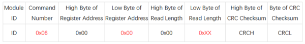
- 说明(0xXX):
- 写入0x01,传感器恢复出厂设置
- 写入0x02,传感器重启
- 波特率设置
- 寄存器地址:0x04
- 发送格式:
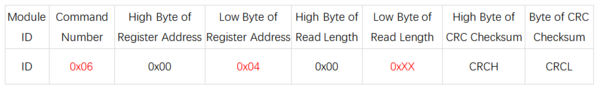
- 说明(0xXX):
- 写入0x00,设置波特率为2400
- 写入0x01,设置波特率为4800
- 写入0x02,设置波特率为9600
- 写入0x03,设置波特率为19200
- 写入0x04,设置波特率为38400
- 写入0x05,设置波特率为57600
- 写入0x06,设置波特率为115200(默认)
- 写入0x07,设置波特率为230400
- 写入0x08,设置波特率为460800
- 写入0x09,设置波特率为921600
- Modbus ID设置
- 寄存器地址:0x1A
- 发送格式:
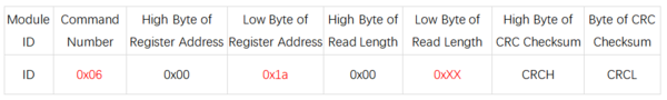
- 说明(0xXX):
- 写入范围为0x00~0xFE,出厂设置默认为0x50
- 测量数据
- 寄存器地址:0x34
- 发送格式:
- 说明:
- 系统模式
- 寄存器地址:0x38
- 发送格式:
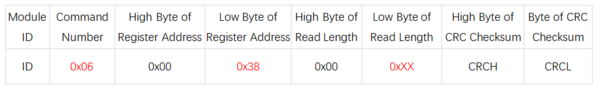
- 说明(0xXX):
- 写入0x00,传感器进入串口打印模式,直接打印字符串。
- 写入0x01,传感器进入Modbus模式(默认)。
- 写入0x02,传感器进入校准模式,校准完成后自动恢复为Modbus模式。
Host Computer
- Hardware Preparation: Single ToF Module, USB to TTL Module, Computer
- Hardware Connection:
- Usage Steps:
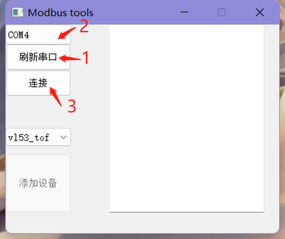
- Connect the Single ToF module to the interface of the USB to TTL module, insert the wired USB to TTL module into the computer's USB port, and open the Host Computer.
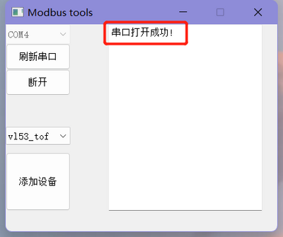
- Click "Refresh Serial Port" in the host software, then select the corresponding port number for the module, and click "Connect" after selecting the port number. At this point, the phrase "Serial Port Opened Successfully" will appear in the dialog box on the right.
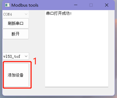
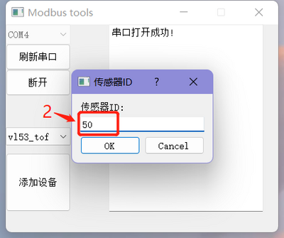
- Click "Add Device" in the bottom left corner, and in the dialog box that appears, enter the module ID (default ID is 0x50), then click "OK".
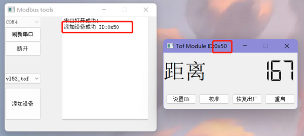
- After successfully setting the ID, a new interface will pop up for viewing the measured distance and configuring the module. At the same time, the phrase "Device Added Successfully ID: 0x50" will appear on the right side of the main interface.
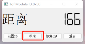
- Calibration:
- Connect the module.
- Place the module 10cm away from a piece of white paper, click the "Calibrate" button to calibrate the module with the corresponding ID.
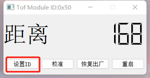
- Set ID:
- Connect the module.
- Click the "Set ID" button, enter a new ID within the range of 01~fe in hexadecimal.
- Restart the module for the changes to take effect. After it takes effect, you need to reconnect the module using the new ID.
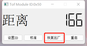
- Factory Reset:
- Connect the module.
- Click the "Factory Reset" button.
- The module will restart for the changes to take effect. After it takes effect, you need to reconnect the module using the default ID (50).
- After a factory reset, the calibration parameters will be cleared, and recalibration is required.
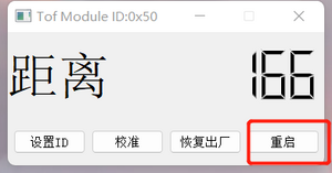
- Restart:
- Connect the module.
- Click the "Restart" button, and the module with the corresponding ID will restart.
Arduino
- Hardware Preparation: Single ToF Module, Arduino
- Hardware Connection:
- Usage Steps:
- Connect the Single ToF module to the Arduino interface, and connect the wired Arduino to the computer.
- Open the code with Arduino IDE and select the corresponding board type and serial port number.
- Modify the IO port number for the serial port where the sensor is connected, based on the actual hardware connection between the sensor and the Arduino.
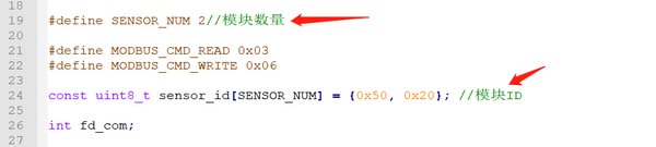
- Modify the number of sensors and sensor IDs according to the actual situation.
- Compile and upload the code.
- Open the Serial Monitor, set the baud rate to 115200, and observe the results.
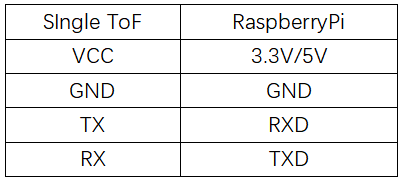
Raspberry Pi
- Hardware Preparation: Single ToF Module, Raspberry Pi
- Hardware Connection:
- Usage Steps
- Burn the Raspberry Pi OS onto an SD card and copy the example code to the system files on the Raspberry Pi.
- Connect the Single ToF module to the Raspberry Pi interface and insert the SD card with the burned OS into the Raspberry Pi.
- Enable the serial port function on the Raspberry Pi.
Execute Command:sudo raspi-config
Select:Interfacing Options
Select:Serial
Select:NO(Would you like a login shell to be accessible over serial?)
Select:YES(Would you like the serial port hardware to be enabled)
Select:YES(The serial login shell is disabled.....)
Restart the Raspberry Pi
- Modify the number of sensors and sensor IDs in the code on the PC according to the actual hardware connection.
- Navigate to the directory where the example code is located and compile it using gcc
sudo gcc vl53_tof.c -o vl53_tof

- Execute the compiled executable file and observe the results
sudo ./vl53_tof
Product Information
FAQ

|
Contact Diustou
Our working hours are: 09:00-18:00 (UTC+8 Monday to Saturday)
|
|


