Experiment 24: Ultrasonic Sensor Experiment
From Diustou Wiki
Contents
Mode Selection

Mode Description
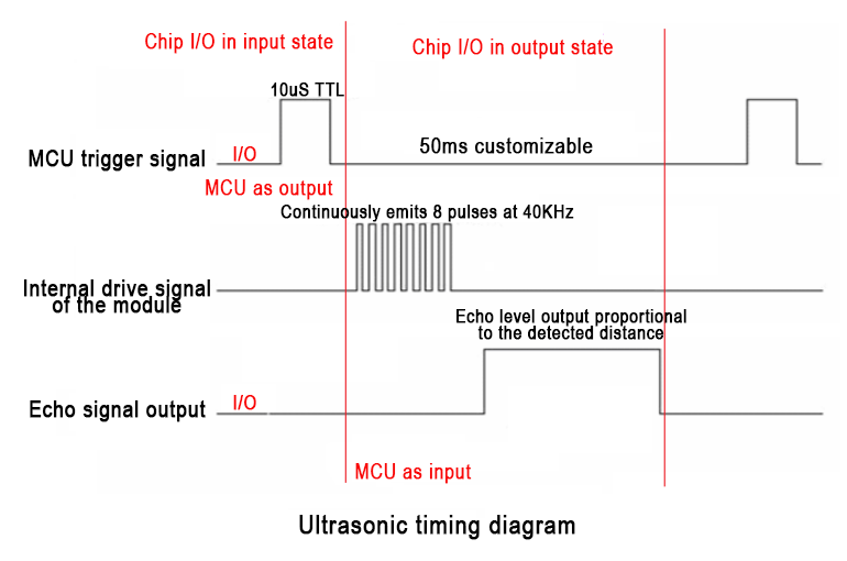
GPIO Mode
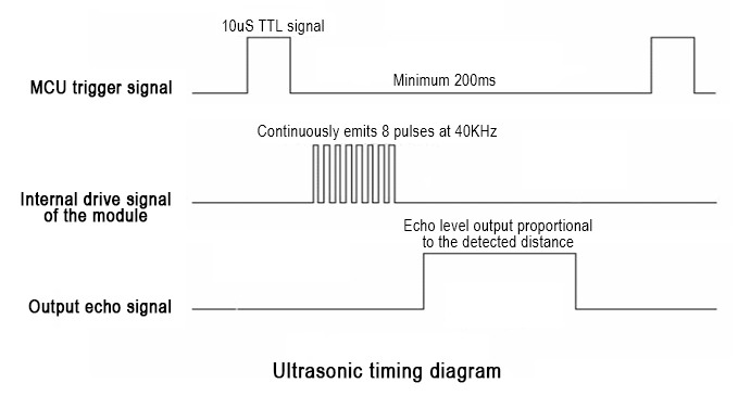
- The working mode is the same as the older version of HC-SR04. The external MCU gives a high-level pulse greater than 10uS to the Trig pin of the module; the module will output a high-level pulse signal proportional to the distance.
- The distance can be calculated based on the pulse width time "T": Distance = T * C / 2 (C is the speed of sound)
- Speed of sound temperature formula: c = (331.45 + 0.61t/°C) m•s⁻¹ (where 331.45 is at 0°C) Where:
- Speed of sound at 0°C: 330.45 M/S
- Speed of sound at 20°C: 342.62 M/S
- Speed of sound at 40°C: 354.85 M/S
- The speed of sound error is about 7% between 0°C and 40°C. In practical applications, if precise distance values are required, temperature compensation must be considered due to the influence of temperature.
_GPIO.png)
IIC Mode
- IIC Address: 0X57
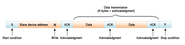
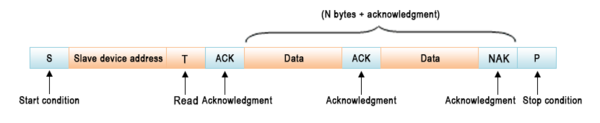
- IIC Transmission Format:
- Writing Data:
- Reading Data:
- Writing Data:
- Command Format:
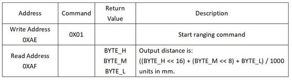
- Write 0X01 to the module to start ranging; wait for more than 200ms (maximum ranging time of the module). Directly read three distance data bytes: BYTE_H, BYTE_M, and BYTE_L.
- Distance calculation formula (in mm):
- Distance = ((BYTE_H << 16) + (BYTE_M << 8) + BYTE_L) / 1000
- Distance = (BYTE_H * 65536 + BYTE_M * 256 + BYTE_L) / 1000
_IIC_1.png)
_IIC_2.png)
_IIC.jpg)
UART Mode
- UART Mode: Baud rate 9600, 1 start bit, 1 stop bit, 8 data bits, no parity bit, no flow control
- Connect to the serial port. The external MCU or PC sends the command 0XA0, and the module returns three distance data bytes after completing the ranging: BYTE_H, BYTE_M, and BYTE_L.
- Distance calculation formula (in mm):
- Distance = ((BYTE_H << 16) + (BYTE_M << 8) + BYTE_L) / 1000
- Distance = (BYTE_H * 65536 + BYTE_M * 256 + BYTE_L) / 1000
1-Wire Mode
- The external MCU is initially set to output mode, giving a high-level pulse greater than 10uS to the I/O pin of the module; after outputting the pulse signal, the MCU is set to input mode, waiting for a high-level pulse signal proportional to the distance from the module; after the measurement is completed, the MCU is set to output mode for the next measurement.
- The speed of sound can be calculated based on the pulse width time "T": Distance = T * C / 2 (C is the speed of sound)
- Speed of sound temperature formula: c = (331.45 + 0.61t/°C) m•s⁻¹ (where 331.45 is at 0°C)
- Speed of sound at 0°C: 330.45 M/S
- Speed of sound at 20°C: 342.62 M/S
- Speed of sound at 40°C: 354.85 M/S
- The speed of sound error is about 7% between 0°C and 40°C. In practical applications, if precise distance values are required, temperature compensation must be considered due to the influence of temperature.

Arduino
- Taking GPIO Mode as an Example
Experimental Phenomenon
- Print the distance measured by the module through the serial port
Circuit Connection

Reference Program
float       distance;
const int   echo=A4;                        // Connect echo to A4 pin
const int   trig=A5;                         // Connect trig to A5 pin
void setup()
{
  Serial.begin(9600);                       // Baud rate 9600
  pinMode(echo,INPUT);                       // Set echo as input
  pinMode(trig,OUTPUT);                      // Set trig as output
  Serial.println(" RCWL-1XXX-TTL 测距开始:");
}
void loop()
{
 digitalWrite(trig,HIGH);
 delayMicroseconds(1);
 digitalWrite(trig,LOW);
 distance  = pulseIn(echo,HIGH);             // Count the high-level time received
 distance  = distance*340/2/10000;            // Calculate distance 1: Speed of sound: 340 M/S 2: Actual distance is 1/2 of the speed of sound distance 3: Counting clock is 1US // Temperature compensation formula: c = (331.45 + 0.61t/°C) m•s⁻¹ (where 331.45 is at 0°C)
 Serial.print("距离: ");
 Serial.print(distance);
 Serial.println("CM");
 delay(30);                                  // Add a 30ms delay after each measurement to prevent inaccurate measurements due to residual waves from the previous measurement when measuring at close range.
 delay(100);                                // Delay for 100ms before the next measurement (optional)
}
Raspberry Pi
- Taking GPIO Mode as an Example
Circuit Connection

Program Execution
Python
- Install the gpiozero library
- You can use the following command to install the library:
sudo apt update
sudo apt install python3-gpiozero
- For other systems on the Raspberry Pi, you can use the following command to install the library:
sudo pip3 install gpiozero
- Run the following command to view the GPIO pin definitions on the Raspberry Pi:
pinout
- Download the Raspberry Pi reference example, unzip the file, copy it to the user directory, and run it:
cd raspberrypi/24/python_gpiozero
python sensor.py
- You can see the Raspberry Pi running the program correctly. To exit, press ctrl+C.
- Command Description: gpiozero.InputDevice(pin, pull_up, active_state)
- Main Parameters:
- pin: GPIO pin number;
- pull_up: Internal pull-up/pull-down resistor setting,
- When set to True, the GPIO pin is pulled high internally.
- When set to False (default), the GPIO pin is pulled low internally.
- When set to None, the GPIO pin is floating, and gpiozero cannot guess the active state, so active_state must be set.
- active_state:
- When set to True, if the hardware pin state is "high," the software pin state is also "high."
- When set to False, the input polarity is reversed, so if the hardware pin state is "high," the software pin state is "low."
- When pull_up is set to None, use this parameter to set the unknown pin active state.
- When pull_up is set to True or False, the pin's active state is automatically assigned.
- Main Parameters:
- Command Description: gpiozero.OutputDevice(pin, active_high, initial_value)
- Main Parameters:
- pin: GPIO pin number,
- active_high: Internal pull-up/pull-down resistor setting,
- When set to True (default), on() sets the pin to High, and off() sets the pin to Low.
- When set to False, on() sets the pin to Low, and off() sets the pin to High.
- initial_value:
- If False (default), all LEDs are initially off.
- If None, the initial state of all LEDs is unstable.
- If True, all LEDs are initially on.
- Command Description: gpiozero.OutputDevice(pin, active_high, initial_value)
- For more commands, please refer to the gpiozero documentation