Difference between revisions of "Experiment 8: Optocoupler Relay Experiment"
From Diustou Wiki
Yousimaier17 (talk | contribs) (Created page with "*Basic Experiment Kits For Arduino *Basic Experiment Kits For Raspberry Pi == 接口说明 == *VCC: Positive terminal for DC power supply of the module *GND: Negative...") |
Yousimaier17 (talk | contribs) |
||
| (3 intermediate revisions by the same user not shown) | |||
| Line 5: | Line 5: | ||
*GND: Negative terminal for DC power supply of the module | *GND: Negative terminal for DC power supply of the module | ||
*IN: Relay signal trigger terminal (can be set to high or low level to control relay activation) | *IN: Relay signal trigger terminal (can be set to high or low level to control relay activation) | ||
| − | Relay Trigger Mode Selection Terminal: When the DIP switch is set to L, it is triggered by a low level; when set to H, it is triggered by a high level. | + | *Relay Trigger Mode Selection Terminal: When the DIP switch is set to L, it is triggered by a low level; when set to H, it is triggered by a high level. |
| − | *NO: Normally open interface of the relay, open before the relay is activated, and short-circuited to COM when activated | + | **NO: Normally open interface of the relay, open before the relay is activated, and short-circuited to COM when activated |
| − | *COM: Common interface of the relay | + | **COM: Common interface of the relay |
| − | *NC: Normally closed interface of the relay, short-circuited to COM before the relay is activated, and open when activated | + | **NC: Normally closed interface of the relay, short-circuited to COM before the relay is activated, and open when activated |
| Line 16: | Line 16: | ||
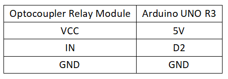
=== Circuit Connection === | === Circuit Connection === | ||
| − | *[[File:实验八:光耦继电器实验_接线1.png| | + | *[[File:实验八:光耦继电器实验_接线1.png|800px]] |
=== Reference Program === | === Reference Program === | ||
| Line 36: | Line 36: | ||
== Raspberry Pi == | == Raspberry Pi == | ||
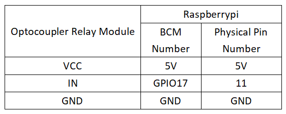
=== Circuit Connection === | === Circuit Connection === | ||
| − | *[[File:实验八:光耦继电器实验_接线2.png| | + | *[[File:实验八:光耦继电器实验_接线2.png|800px]] |
=== Program Execution === | === Program Execution === | ||
| Line 46: | Line 46: | ||
sudo apt install python3-gpiozero | sudo apt install python3-gpiozero | ||
</pre> | </pre> | ||
| − | : * For other systems on the Raspberry Pi, you can install the library using: | + | :* For other systems on the Raspberry Pi, you can install the library using: |
<pre> | <pre> | ||
sudo pip3 install gpiozero | sudo pip3 install gpiozero | ||
</pre> | </pre> | ||
| − | : * Run the following command to view the GPIO pin definitions on the Raspberry Pi: | + | :* Run the following command to view the GPIO pin definitions on the Raspberry Pi: |
<pre> | <pre> | ||
pinout | pinout | ||
Latest revision as of 14:02, 11 February 2025
Contents
接口说明
- VCC: Positive terminal for DC power supply of the module
- GND: Negative terminal for DC power supply of the module
- IN: Relay signal trigger terminal (can be set to high or low level to control relay activation)
- Relay Trigger Mode Selection Terminal: When the DIP switch is set to L, it is triggered by a low level; when set to H, it is triggered by a high level.
- NO: Normally open interface of the relay, open before the relay is activated, and short-circuited to COM when activated
- COM: Common interface of the relay
- NC: Normally closed interface of the relay, short-circuited to COM before the relay is activated, and open when activated
Arduino
Experimental Phenomenon
- The relay is energized once every second, and simultaneously, the LED indicator on the module lights up every second.
Circuit Connection
Reference Program
int relay = 2; // Relay activation trigger signal - high level active;
void setup()
{
 pinMode(relay,OUTPUT); // Define port as output;
}
void loop()
{
 digitalWrite(relay,HIGH); // Activate relay;
 delay(1000);
 digitalWrite(relay,LOW); // Deactivate relay;
 delay(1000);
}
Raspberry Pi
Circuit Connection
Program Execution
Python
- Install the gpiozero library
- You can install the library using the following commands:
sudo apt update
sudo apt install python3-gpiozero
- For other systems on the Raspberry Pi, you can install the library using:
sudo pip3 install gpiozero
- Run the following command to view the GPIO pin definitions on the Raspberry Pi:
pinout
- Download the Raspberry Pi reference examples, unzip the files, copy them to your user directory, and run:
cd raspberrypi/8/python_gpiozero
python relay.py
- You should now see the Raspberry Pi running the optocoupler relay program correctly. To exit, press ctrl+C.
- Command explanation: gpiozero.LED(pin, pwm, active_high, initial_value)
- Main parameters:
- pin: GPIO pin number,
- active_high:
- When set to True (default), connect the LED's negative terminal to GND and the other terminal to the GPIO pin.
- When set to False, connect the LED's negative terminal to the GPIO pin and the other terminal to the 3.3V pin.
- initial_value:
- If False (default), the LED initial state is off.
- If None, the LED pin is in an unstable state.
- If True, the LED initial state is on.
- Main parameters:
- For more commands, please refer to the gpiozero documentation

