Experiment 5: Matrix Keypad Experiment
From Diustou Wiki
Contents
Scanning Principle
- The structure of a matrix keypad is more complex than that of an independent keypad, and its recognition by a microcontroller is also more complicated. There are two scanning methods for matrix keypads: row-column scanning and row-by-row/column-by-column scanning. Row-column scanning, also known as the line inversion method, is suitable for situations where the matrix keypad is continuously controlled by the I/O ports of the microcontroller. Row-by-row/column-by-column scanning is suitable for situations where the matrix keypad is connected to any I/O ports of the microcontroller. In practical microcontroller applications, row-column scanning is more commonly used.
- Taking a 4x4 matrix keypad as an example, the four row lines (starting from the first row) are connected to P1.0-P1.3 of the microcontroller, and the four column lines (starting from the first column) are connected to P1.4-P1.7.
Row-Column Scanning
- Set the high four bits of port P1 to output high level and the low four bits to output low level. At this time, the column lines are pulled high and the row lines are pulled low. If a key is pressed, the level of a certain column will be pulled low. Read the level of the high four bits (four columns) of port P1. If the read value is not all high, it indicates that a key is pressed, and the column can be determined based on the read value. Then, set the high four bits of port P1 to output low level and the low four bits to output high level. Read the level of the low four bits (four rows) of port P1. At this time, the read value is no longer all high, and the row can be determined based on the read value. By combining the results of the two readings, the key value of the current key can be obtained, thereby determining the position of the pressed key.
Row-by-Row/Column-by-Column Scanning
- The essence of the row-by-row/column-by-column scanning method is similar to the row-column scanning method, which is to output low level to a certain row/column and high level to the other seven. At this time, read the level change. If it is low, it indicates that a key is pressed, and the position of the pressed key can be judged based on the read key value.
- The specific operation is as follows: set the first row to low level and the other three rows and four columns to high level. Read the data of the column lines. If the column lines are not all high, it indicates that a key on the first row is pressed, and the specific column of the first row can be judged based on the read data. If the column lines are all high, set the second row to low level and the other three rows and four columns to high level. Read the data of the column lines to determine if a key is pressed. Repeat the above actions, and so on.
Arduino
Experimental Phenomenon
- Output the key value when a button is pressed via serial port.
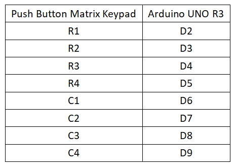
Circuit Connection
Reference Program
int R[] = {2,3,4,5};
int C[] = {6,7,8,9};
void setup() {
  Serial.begin(9600);
  for (int i = 0; i < 4; i++)
  {
    pinMode(R[i], INPUT_PULLUP);
    pinMode(C[i], OUTPUT);
  }
}
void loop() {
// Set column lines to 0
  for (int i = 0; i < 4; i++)
  {
    digitalWrite(C[i], LOW);
  }
  if (!digitalRead(R[0]) || !digitalRead(R[1]) || !digitalRead(R[2])|| !digitalRead(R[3]))
  {
    delay(10);
    if (!digitalRead(R[0]) || !digitalRead(R[1]) || !digitalRead(R[2])|| !digitalRead(R[3]))
    {
      digitalWrite(C[0], LOW);// Scan first column
      digitalWrite(C[1], HIGH);
      digitalWrite(C[2], HIGH);
      digitalWrite(C[3], HIGH);
      for (int j = 0; j < 4; j++)
      {
        if (!digitalRead(R[j]))
        {
          Serial.print("S");
          Serial.print(j * 4 + 1);// Output button number in the serial monitor
          Serial.println(" has been pressed");
          while (!digitalRead(R[j]));
          Serial.println("The button has been loosened");
        }
      }
      digitalWrite(C[0], HIGH);// Scan second column
      digitalWrite(C[1], LOW);
      digitalWrite(C[2], HIGH);
      digitalWrite(C[3], HIGH);
      for (int j = 0; j < 4; j++)
      {
        if (!digitalRead(R[j]))
        {
          Serial.print("S");
          Serial.print( j * 4 + 2);
          Serial.println(" has been pressed");
          while (!digitalRead(R[j]));
          Serial.println("The button has been loosened");
        }
      }
      digitalWrite(C[0], HIGH);// Scan third column
      digitalWrite(C[1], HIGH);
      digitalWrite(C[2], LOW);
      digitalWrite(C[3], HIGH);
      for (int j = 0; j < 4; j++)
      {
        if (!digitalRead(R[j]))
        {
          Serial.print("S");
          Serial.print(j * 4 + 3);
          Serial.println(" has been pressed");
          while (!digitalRead(R[j]));
          Serial.println("The button has been loosened");
        }
      }
      digitalWrite(C[0], HIGH);// Scan fourth column
      digitalWrite(C[1], HIGH);
      digitalWrite(C[2], HIGH);
      digitalWrite(C[3], LOW);
      for (int j = 0; j < 4; j++)
      {
        if (!digitalRead(R[j]))
        {
          Serial.print("S");
          Serial.print(j * 4 + 4);
          Serial.println(" has been pressed");
          while (!digitalRead(R[j]));
          Serial.println("The button has been loosened");
        }
      }
    }
  }
}
Notes
- The button connection pins should be configured as input pull-up mode, so that the pin can maintain a high potential without an external signal input, written as: pinMode(9, INPUT_PULLUP);
- If simply written as: pinMode(9, INPUT), the state of the pin will be unstable, with 0 and 1 changing irregularly, affecting program judgment.
Raspberry Pi
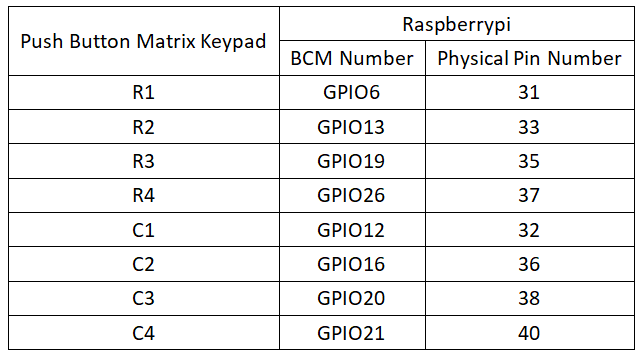
Circuit Connection
Program Execution
Python
- Install the gpiozero library
- You can use the following command to install the library:
sudo apt update
sudo apt install python3-gpiozero
- For other systems on the Raspberry Pi, you can use the following command to install the library:
sudo pip3 install gpiozero
- Run the following command to view the GPIO pin definitions on the Raspberry Pi:
pinout
- Download the Raspberry Pi reference example, unzip the file, copy it to the user directory, and run:
cd raspberrypi/5/python_gpiozero
python button.py
- You should see the Raspberry Pi running the matrix keypad program correctly, and pressing any button will print the corresponding key value on the serial port. To exit, press ctrl+C.
- Command description: gpiozero.ButtonBoard(pin, pull_up, active_state, bounce_time, hold_time, hold_repeat)
- Main parameters:
- pin: GPIO pin number;
- pull_up: Internal pull-up/pull-down resistor setting,
- When set to True (default), the GPIO pin is pulled high, and the other end of the button should be connected to ground.
- When set to False, the GPIO pin is pulled low, and the other end of the button should be connected to 3V3.
- When set to None, the GPIO pin is floating, and gpiozero cannot guess the active state; you must set active_state.
- active_state:
- When set to True, the software pin state is also "high" when the hardware pin state is "high".
- When set to False, the input polarity is reversed; when the hardware pin state is "high", the software pin state is "low".
- When pull_up is set to None, use this parameter to set the unknown pin active state.
- When pull_up is set to True or False, the pin's active state is automatically assigned.
- bounce_time: Software debounce time. Generally, switches are unstable for about 20ms, known as "switch bounce".
- When set to None, software debounce compensation is not performed; otherwise, this parameter is the length of time (in seconds) that the component ignores after an initial change, with a default of 1s.
- hold_time: The time after pressing the button until when_held is triggered, in seconds.
- hold_repeat:
- If True, as long as the button remains pressed, when_held will be continuously triggered every hold_time seconds.
- If False, when_held will only be triggered once.
- Main parameters:
- Command description: LEDBoard(pin, pwm, active_high, initial_value)
- Main parameters:
- pin: GPIO pin number,
- pwm:
- If True, constructs a PWMLED instance for each pin.
- If False (default), constructs a regular LED instance.
- active_high: Internal pull-up/pull-down resistor setting,
- When set to True (default), on() sets the pin to High, and off() sets the pin to LOW.
- When set to False, on() sets the pin to LOW, and off() sets the pin to High.
- initial_value:
- If False (default), all LEDs are initially off.
- If "None", all LEDs are initially in an unstable state.
- If True, all LEDs are initially on.
- Main parameters:
- For more commands, please refer to the gpiozero documentation

