Experiment 34: Fan Speed Adjustment Experiment
From Diustou Wiki
Revision as of 17:57, 12 February 2025 by Yousimaier17 (talk | contribs) (Created page with "*Basic Experiment Kits For Arduino *Basic Experiment Kits For Raspberry Pi == Notes == *DC motors are the most common type of motors. A DC motor typically has only two...")
Contents
Notes
- DC motors are the most common type of motors. A DC motor typically has only two leads, one positive and one negative. If these two leads are directly connected to a battery, the motor will rotate. If the leads are switched, the motor will rotate in the opposite direction.
- Do not drive the motor directly from the Arduino board pins. This could damage the circuit board. Use a driver circuit or IC.
Arduino
Experimental Phenomenon
- Control the speed of a DC motor with a potentiometer.
Circuit Connection

Reference Program
int Led=13;//Define LED pin
int buttonpin=3; //Define obstacle avoidance sensor pin
int val;//Define digital variable val
void setup()
{
  pinMode(Led,OUTPUT);//Set LED as output pin
  pinMode(buttonpin,INPUT);//Set obstacle avoidance sensor as input pin
}
void loop()
{
  val=digitalRead(buttonpin);//Read the value from digital pin 3 and assign it to val
  if(val==LOW) //When the obstacle avoidance sensor detects a signal, the LED blinks
  {
    digitalWrite(Led,HIGH);
  }
  else
  {
    digitalWrite(Led,LOW);
  }
}
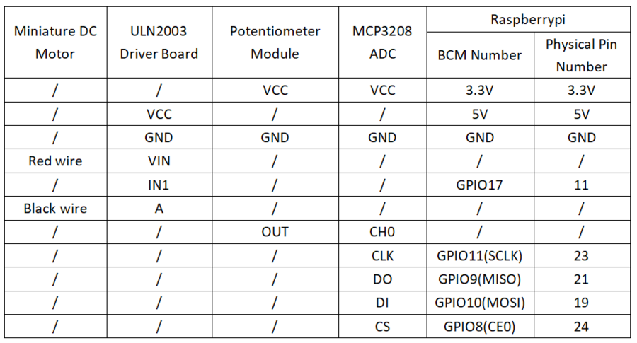
Raspberry Pi
Circuit Connection
 *
*

Program Execution
Python
- Install the gpiozero library
- You can use the following command to install the library:
sudo apt update
sudo apt install python3-gpiozero
- For other systems on the Raspberry Pi, you can use the following command to install the library:
sudo pip3 install gpiozero
- Run the following command to view the GPIO pin definitions on the Raspberry Pi:
pinout
- Set the DIP switch on the ULN2003 driver module to the ON position
- Download the Raspberry Pi reference example, unzip the file, copy it to the user directory, and run it:
cd raspberrypi/34/python_gpiozero
python motor.py
- You can see the Raspberry Pi running the program correctly. To exit, press ctrl+C.
- Command explanation: gpiozero.PWMOutputDevice(pin, active_high, initial_value,
- Main parameters:
- pin: GPIO pin number,
- active_high: Internal pull-up/pull-down resistor setting,
- When set to True (default), on() sets the pin to High and off() sets the pin to LOW.
- When set to False, on() sets the pin to LOW and off() sets the pin to High.
- initial_value: If 0 (default), the device's duty cycle is initially 0. You can specify other values between 0 and 1 as the initial duty cycle. Note that you cannot specify None (unlike the parent class) because there is no way to tell the PWM not to change the state of the pin.
- frequency: The pulse frequency (in Hz) used to drive the device. The default is 100Hz.
- Main parameters:
- For more commands, please refer to the gpiozero documentation