Basic Experiment Kits For Raspberry Pi
From Diustou Wiki
Revision as of 10:10, 23 January 2025 by Yousimaier17 (talk | contribs) (Created page with "{{Product |images=400px |categories= {{Category|Raspberry Pi}} |brand=Diustou |features= * Basic Experiment Kits...")
| |||||||||||||||||||
| |||||||||||||||||||
| |||||||||||||||||||
| |||||||||||||||||||

Contents
产品说明
- 400-hole #Breadboard x1
- 400 Point Breadboard
- #Jumper Wires
- 100mm Male-to-Male x20
- 100mm Male-to-Female x20
- 200mm Male-to-Male x20
- 200mm Male-to-Female x20
- 4x4 #Push Button Matrix Keypad x1
- 4*4 Push Button Matrix Keypad
- #MCP3208 ADC x1
- MCP3208 ADC (12bit, SPI, 8)
- #LCD1602 x1
- #Miniature DC Motor x1
- Miniature DC Motor With Fan Blades (130)
- #5-Wire 4-Phase DC Stepper Motor (5V) x1
- 5-Wire 4-Phase DC Stepper Motor (5V)
- Module Combination Board x1
- #Traffic Light Module x1
- Traffic Light
- #RGB Module (CC) x1
- RGB LED(CC)
- #Potentiometer Module(10K) x1
- Potentiometer(10K)
- #Independent key Module x1
- Independent key Module
- #Active Buzzer Module x1
- Active Buzzer
- #Passive Buzzer Module x1
- Passive Buzzer
- #Optocoupler Relay Module x1
- Relay Module With Optocoupler
- #DHT11 Sensor Module x1
- DHT11 Sensor
- #DS18B20 Sensor Module x1
- DS18B20 Sensor
- #NTC Thermistor Sensor Module x1
- NTC Thermistor Sensor
- #Photoresistor Sensor Module x1
- Photoresistor Sensor
- #Flame Detection Sensor Module x1
- Flame Detection Sensor
- #Infrared Obstacle Avoidance Sensor Module x1
- Infrared Obstacle Avoidance Sensor
- #Infrared Tracking Sensor Module x1
- Infrared Tracking Sensor
- #AM312 Human Body Induction Module x1
- AM312 Sensor
- #Laser Sensor Module x1
- Laser Sensor
- #Grayscale Sensor Module x1
- Grayscale Sensor
- #Magnetron Sensor Module x1
- Magnetron Sensor
- #3144E Hall Sensor Module x1
- 3144E Hall Sensor
- #SW-18010P Vibration Sensor Module x1
- SW-18010P Vibration Sensor
- #SW-520D Tilt Switch Module x1
- SW-520D Tilting Switch Module
- #TTP223 Touch Switch Module x1
- TTP223 Touch Switch
- #Ultrasonic Distance Sensor Module x1
- Ultrasonic Distance Sensor
- #Sound Sensor Module x1
- Sound Sensor
- #MQ-2 Gas Sensor Module x1
- MQ-2 Gas Sensor
- #Liquid Level Sensor Module x1
- Liquid Level Sensor
- #Soil Moisture Sensor Module x1
- Soil Moisture Sensor
- #8x8 MAX7219 Dot Matrix Module x1
- 8x8 MAX7219 Dot Matrix
- #Digital Tube Display Module(74HC595) x1
- Digital Tube Display Module (74HC595)
- #LCD1602 IIC Module x1
- LCD1602 IIC Module
- #ULN2003 Driver Board x1
- ULN2003 Drive Board
- #Traffic Light Module x1
Module Description
Main Components
Breadboard
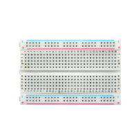
- The breadboard has two columns of power rails on each side. Each column consists of five holes in a group. The holes within the same group and between different groups are electrically connected, but the holes between columns are not connected.
- The holes in the middle section are divided into two sides by a central groove. On each side, every row of five holes forms a group, and the holes within the same group are electrically connected, but the holes between rows are not interconnected.


Jumper Wires
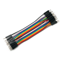
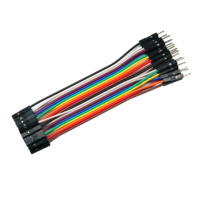
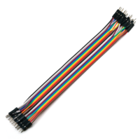
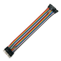
- Specifications: 100mm male-to-male, 100mm male-to-female, 200mm male-to-male, 200mm male-to-female
- Pitch: 2.54mm
- Voltage rating: 300V
- Maximum current: 2A
- Outer diameter of the wire: 1.4mm
- Wire core specification: 12 fully copper cores, core diameter 0.09mm


Basic Module
Traffic Light Module
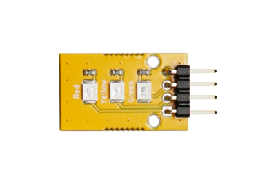
- There are two types of traffic lights. The one for motor vehicles is called the vehicle traffic light, typically consisting of red, yellow, and green (green being blue-green) lights used to direct traffic. When the green light is on, vehicles are allowed to pass. When the yellow light flashes, vehicles that have already crossed the stop line can continue, while those that haven't should slow down and stop at the stop line and wait. When the red light is on, vehicles are prohibited from passing. The one for pedestrians is called the pedestrian crossing light, usually consisting of red and green (green being blue-green) lights used to direct pedestrian traffic. Red means stop, and green means go.
- Parameter Description:
- Size: 1525mm
- Mounting Hole: 2mm
- Colors: Red, Yellow, Green
- LED: SMD
- Brightness: Normal Brightness
- Voltage: 3.3V/5V
- Current Limiting Resistor: 330Ω
- Input: Digital Level
- Control Method: High-level control, with independent control of red, yellow, and green lights.
- Reference Routine: Experiment 1: Traffic Light Experiment

RGB Module (CC)
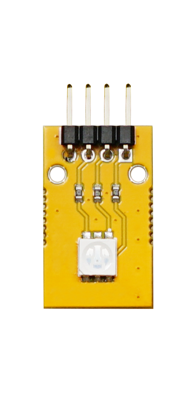
- The RGB module can emit a variety of colors. The primary colors of red, green, and blue can be mixed in varying brightness to produce a range of colors, allowing the RGB-LED to emit colored light by controlling the circuit.
- Parameter Description:
- Size: 1525mm
- Mounting Hole: 2mm
- Colors: Red, Green, Blue
- LED: SMD
- Brightness: Normal Brightness
- Operating Voltage: 3.3V/5V
- Current Limiting Resistor: 330Ω
- Input: PWM
- Control Method: High-level control, with independent control of red, green, and blue.
- Reference Routine: Experiment 2: RGB Color Light Experiment

Potentiometer Module
- A potentiometer is essentially a variable resistor. It is called a potentiometer because its function in a circuit is to obtain an output voltage that has a certain relationship with the input voltage (applied voltage). It is usually manufactured to maintain its original characteristics regardless of how long it is used. When used as a position sensor, a potentiometer can be a linear or rotary position sensor. The potentiometer outputs a voltage value that is proportional to the position of the slider along the variable resistor. Due to factors such as temperature changes, wear, and dirt between the slider and the variable resistor, which can cause resistance changes and affect the accuracy of the potentiometer, potentiometers have relatively low accuracy. However, with the development of materials, especially conductive plastics, potentiometers can maintain their original characteristics even after long-term use, and their performance has also been improved.
- Parameter Description:
- Size: 1525mm
- Mounting Hole: 2mm
- Operating Voltage: 3.3V/5V
- Resistance: 10K
- Accuracy: ±20%
- Output: Analog Voltage
- Reference Routine: Experiment 3: Rotary Potentiometer Experiment

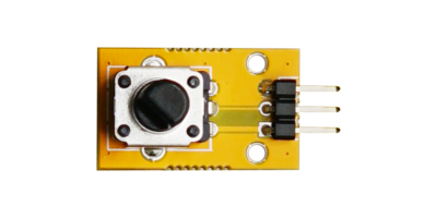
Independent key Module
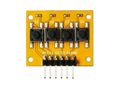
- The independent button module primarily uses tactile push-button switches, which can serve as electronic switches and be used as external devices for platforms such as Arduino and microcontrollers. It features a simple circuit and is easy to use.
- When in use, it needs to be connected to VCC and GND. When the button is not pressed, it is at a low level; when the button is pressed, it is at a high level.
- Parameter Description:
- Size: 2530mm
- Mounting Hole: 2mm
- Operating Voltage: 3.3V/5V
- Reference Routine: Experiment 4: Button Control LED Experiment

=
Push Button Matrix Keypad =
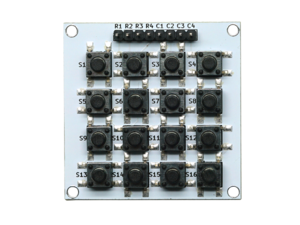
- A matrix keypad, used as an external device for microcontrollers, arranges buttons in a matrix format when a large number of buttons are required. This arrangement reduces the occupation of I/O ports and improves the utilization rate of the microcontroller. In a matrix keypad, each horizontal line is connected to each vertical line through a button, allowing an 8-bit port of the microcontroller to control 44=16 matrix buttons. This method doubles the number of buttons that can be controlled compared to directly controlling buttons with ports. The difference becomes more pronounced as the number of lines increases.
- Example Routine: Experiment 5: Matrix Keypad Experiment

MCP3208 ADC
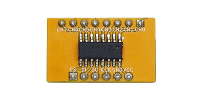
- The MCP3208 12-bit Analog-to-Digital Converter (ADC) combines high performance and low power consumption in a small package, making it an ideal choice for embedded control applications. The MCP3208 features a Successive Approximation Register (SAR) architecture and an industry-standard SPI serial interface, allowing 12-bit ADC functionality to be added to any microcontroller. The MCP3208 offers 100k samples/second, 8 input channels, and low power consumption (typically 5nA standby, maximum 400μA).
- Datasheet: MCP3208
- Pin Description:


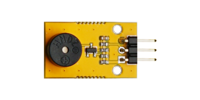
Active Buzzer Module
- An active buzzer has a simple oscillating circuit inside, which can convert a constant DC signal into a pulse signal of a certain frequency, thereby achieving alternating magnetic fields to drive the diaphragm to vibrate and produce sound. However, some active buzzers can also operate under specific AC signals, but the voltage and frequency of the AC signal are very high, so this operating mode is generally not used.
- Parameter Description:
- Size: 1525mm
- Mounting Hole: 2mm
- Operating Voltage: 5V
- Driver: S8050 transistor
- Trigger: High-level trigger
- Resonant Frequency: 2.7kHz
- Reference Routine: Experiment 6: Active Buzzer Module Experiment

Passive Buzzer Module
- A passive buzzer utilizes the principle of electromagnetic induction. When an alternating current is applied to the voice coil, the resulting electromagnet attracts or repels the permanent magnet, driving the diaphragm to produce sound. Applying a direct current can only continuously push the diaphragm and cannot produce sound; it can only generate sound when turned on or off.
- A passive buzzer has no driving circuit inside, and its operating signal is a square wave. If a DC signal is directly applied to a passive buzzer, there will be no sound because the magnetic circuit remains unchanged, and the diaphragm is always in an attracted state, unable to vibrate and produce sound.
- Parameter Description:
- Size: 1525mm
- Mounting Hole: 2mm
- Operating Voltage: 5V
- Driver: S8550 transistor
- Trigger: Low-level trigger
- Input: PWM
- Sound Pressure: ≥80dB
- Resistance: 16±5Ω
- Resonant Frequency: 2.7KHz
- Reference Routine: Experiment 7: Passive Buzzer Module Experiment

Optocoupler Relay Module
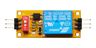
- A relay is an electrically controlled device that causes a predetermined step change in the controlled variable in the electrical output circuit when the change in the input variable (excitation) meets the specified requirements. It has an interactive relationship between the control system (also known as the input circuit) and the controlled system (also known as the output circuit). Typically used in automated control circuits, it is essentially an "automatic switch" that uses a small current to control the operation of a large current. Therefore, it plays a role in automatic adjustment, safety protection, and circuit switching in the circuit.
- Parameter Description:
- Size: 1842mm
- Mounting Hole: 2mm
- Operating Voltage: 5V
- Control Signal: High level (greater than 4V) / Low level (less than 1V)
- Trigger Current: 0-5mA
- Load Current: 10A
- Equipped with power indicator and relay status indicator.
- Features diode freewheeling protection and optocoupler protection.
- Reference Routine: Experiment 8: Optocoupler Relay Experiment

Temperature Sensor
DHT11 Sensor Module
- The DHT11 digital temperature and humidity sensor is a composite sensor that includes a calibrated digital signal output for both temperature and humidity. It is internally controlled by an 8-bit microcontroller, which manages a resistive humidity sensing element and an NTC temperature measuring element. Compared to the DS18B20 digital temperature sensor, the DHT11 can detect both temperature and humidity. The DHT11 sensor uses a single-wire serial interface, and its Dout pin can be directly connected to a microcontroller's I/O port after being pulled up with a 5K resistor. The signal transmission distance can reach over 20 meters, and it has advantages such as strong anti-interference ability, high cost-effectiveness, and fast response speed. It utilizes dedicated digital module acquisition technology and temperature and humidity sensing technology to ensure the product has extremely high reliability and excellent long-term stability.
- Parameter Description:
- Size: 1525mm
- Mounting Hole: 2mm
- Sensor: DHT11
- Operating Voltage: 3V-5.5V
- Operating Current: Average 0.5mA
- Humidity Measurement Range: 5-95%RH
- Humidity Measurement Accuracy: ±5%RH
- Humidity Resolution: 1%RH, 8-bit
- Temperature Measurement Range: -20-60℃
- Temperature Measurement Accuracy: ±2℃
- Temperature Resolution: 1℃, 8-bit
- Sampling Period: ≥2s
- Reference Routine: Experiment 9: DHT11 Temperature and Humidity Sensor Experiment

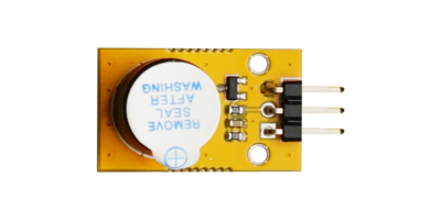
DS18B20 Sensor Module
- The DS18B20 adopts a 1-Wire bus protocol, which enables bidirectional data transmission on a single data line. Since microcontrollers do not natively support the 1-Wire bus protocol, a software approach must be used to simulate the protocol sequence to access the DS18B20 chip. As the DS18B20 reads and writes data on a single I/O line, there are strict timing requirements for the data bits being read and written. It has a rigorous communication protocol to ensure the accuracy and integrity of each data transmission. This protocol defines several signal timing sequences: initialization sequence, read sequence, and write sequence. In all sequences, the microcontroller acts as the master device, and the DS18B20 as the slave device. Every command and data transmission starts with the master initiating the write sequence. If data is required from the DS18B20, after sending a write command, the master needs to initiate the read sequence to receive the data.
- Parameter Description:
- Size: 1525mm
- Mounting Hole: 2mm
- Sensor: DS18B20U
- Operating Voltage: DC5V
- Adjustable Resolution Range: 9-12 bits
- Temperature Measurement Range: -55~+125℃
- Temperature Measurement Accuracy: 0.4℃
- Signal Output: Digital Signal
- Reference Routine: Experiment 10: DS18B20 Temperature Sensor Experiment

NTC Thermistor Sensor Module
- Thermistors are a type of sensitive component, classified into Positive Temperature Coefficient thermistors (PTC) and Negative Temperature Coefficient thermistors (NTC) based on their temperature coefficients. The typical characteristic of a thermistor is its sensitivity to temperature, exhibiting different resistance values at different temperatures. A PTC thermistor has a higher resistance at higher temperatures, while an NTC thermistor has a lower resistance at higher temperatures; both belong to semiconductor devices.
- Parameter Description:
- Size: 1535mm
- Mounting Hole: 2.5mm
- Utilizes an NTC thermistor sensor with good sensitivity
- Operating Voltage: 3.3V-5V
- Resistance (at 25℃): 10kΩ
- B-value (25℃/50℃): 3950K
- Resistance Accuracy: ±1%
- Power: 200mW
- B-value Accuracy: ±1%
- Maximum Steady-state Current (at 25℃): 440uA
- Operating Temperature: -55℃~+125℃
- Reference Routine: Experiment 11: Thermistor Sensor Experiment

Optical Sensor
Photoresistor Sensor Module
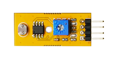
- A photoresistor is a special type of resistor made from semiconductor materials such as cadmium sulfide or selenium sulfide, operating based on the internal photoelectric effect. The stronger the light, the lower its resistance becomes. As the light intensity increases, the resistance rapidly decreases, with the bright resistance dropping to below 1KΩ. The photoresistor is highly sensitive to light and exhibits a high resistance state in the absence of light, with a dark resistance typically reaching up to 1.5MΩ. The unique properties of photoresistors will find extremely wide applications with the development of technology.
- Parameter Description:
- Size: 1535mm
- Mounting Hole: 2.5mm
- Sensor: GL5516
- Operating Voltage: 3.3V-5V
- Dark Resistance: 500kΩ
- Bright Resistance @ 10Lux: 5kΩ~10kΩ
- Maximum Voltage: 150V
- Spectral Peak (Wavelength): 540nm
- Reference Routine: Experiment 12: Photoresistor Sensor Experiment

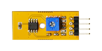
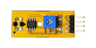
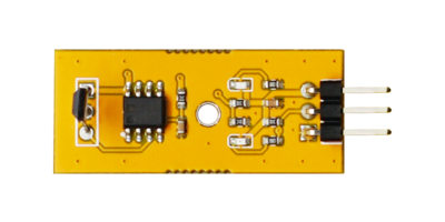
Flame Detection Sensor Module
- The flame sensor detects flames by using a specialized infrared receiver tube to capture the infrared wavelengths emitted by the flame. It can detect flames or light sources/heat sources within the wavelength range of 760nm to 1100nm, with a detection angle of approximately 60 degrees. Its sensitivity reaches its peak when the infrared wavelength is around 940 nanometers. The sensor is equipped with an M3 mounting hole for easy adjustment and fixation. It uses a wide-voltage LM393 comparator, providing a clean signal, good waveform, and strong driving capability exceeding 15mA. It also comes with an adjustable precision potentiometer for sensitivity adjustment.
- Parameter Description:
- Size: 1535mm
- Mounting Hole: 2.5mm
- Sensor: JNJ-PT2835F30-A1
- Operating Voltage: 5V
- Wavelength: 940nm
- Photocurrent: 1.7mA
- Acceptance Angle: 30°
- Reference Routine: Experiment 13: Flame Sensor Experiment

Infrared Obstacle Avoidance Sensor Module
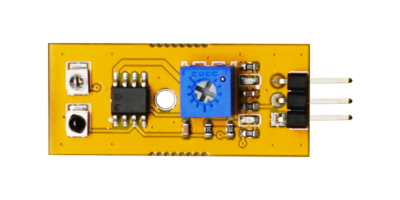
- This sensor module has strong adaptability to ambient light and features a pair of infrared emitting and receiving tubes for detecting obstacles. The detection distance can be adjusted using a potentiometer knob, with clockwise rotation increasing the effective distance. The module's effective distance range is 2~5cm. The sensor is equipped with an M3 mounting hole for easy adjustment and fixation. It uses a wide-voltage LM393 comparator, providing a clean signal, good waveform, and strong driving capability exceeding 15mA. It can be applied to various scenarios such as production line piece counting, robot obstacle avoidance, and black-and-white line tracking.
- Product Description
- Size: 1535mm
- Mounting Hole: 2.5mm
- Sensors: JNJ-PT2835F30-A1 and XYC-IR76C30-LX4
- Operating Voltage: 5V
- Wavelength: 940nm
- Acceptance Angle: 30°
- Reference Routine: Experiment 14: Infrared Obstacle Avoidance Sensor Experiment

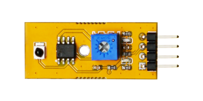
Infrared Tracking Sensor Module
- The infrared tracking sensor utilizes the TCRT5000 sensor. When the infrared emitting diode of the TCRT5000 continuously emits infrared light, and the emitted infrared light is not reflected back or is reflected back but with insufficient intensity, the phototransistor remains in an off state. At this time, the output terminal of the module is at a low level, and the indicator LED remains off. When a detected object appears within the detection range, the infrared light is reflected back with sufficient intensity, causing the phototransistor to saturate. At this point, the output terminal of the module is at a high level, and the indicator LED is illuminated.
- Parameter Description:
- Size: 1535mm
- Mounting Hole: 2.5mm
- Sensor: TCRT5000L
- Operating Voltage: 3.3V-5V
- Detection Distance: 1mm~25mm
- Output Form: Digital Switch Signal
- The tracking module typically requires a distance of 1-2cm from the black line to be detected.
- Reference Routine: Experiment 15: Infrared Tracking Sensor Experiment

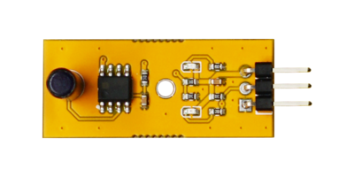
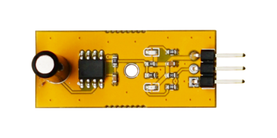
AM312 Human Body Induction Module
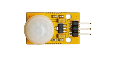
- The AM312 is a pyroelectric infrared sensor that integrates a digital intelligent control circuit and a human body detection sensor within an electromagnetic shielding cover. The human body detection sensor couples the sensed human movement signals to a digital intelligent integrated circuit chip through a very high impedance differential input circuit. The digital intelligent integrated circuit converts the signals into 15-bit ADC digital signals. When the PIR signal exceeds a selected digital threshold, a delayed REL level output is generated. All signal processing is done on the chip.
- Parameter Description:
- Size: 1525mm
- Mounting Hole: 2mm
- Sensor: AM312
- Operating Voltage: DC5V
- Quiescent Power Consumption: Less than 15 microamperes
- Level Output: High 3.3V, Low 0V
- Delay Time: Adjustable (0.3 seconds ~ 18 seconds)
- Blockout Time: 2.5 seconds
- Sensing Range: Less than 120-degree cone angle
- Operating Temperature: -20 ~ +85 degrees Celsius
- Sensing Lens Size: (Diameter) 23mm (default)
- Reference Routine: Experiment 16: Human Body Infrared Pyroelectric Sensor Experiment

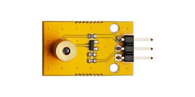
Laser Sensor Module
- Laser is another major invention of humanity in the 20th century, following nuclear energy, computers, and semiconductors, and is known as "the fastest knife," "the most accurate ruler," and "the brightest light." Its English name, Light Amplification by Stimulated Emission of Radiation, fully expresses the main process of laser creation. The principle of laser was discovered as early as 1916 by the renowned American physicist Albert Einstein. The light from stimulated emission of atoms is hence named "laser": when electrons in an atom absorb energy and transition from a low energy level to a high energy level, and then fall back to the low energy level, the released energy is emitted in the form of photons. The beam of photons (laser) induced (or stimulated) has highly consistent optical properties. This makes lasers superior to conventional light sources in terms of monochromaticity, brightness, and directionality.
- Lasers are widely used in laser marking, laser welding, laser cutting, optical fiber communication, laser ranging, laser radar, laser weapons, laser discs, laser vision correction, laser cosmetics, laser scanning, laser mosquito killers, LIF non-destructive testing technology, and more. Laser systems can be classified into continuous-wave lasers and pulsed lasers.
- Parameter Description:
- Size: 1525mm
- Mounting Hole: 2mm
- Power Supply Voltage: 5VDC
- Operating Current: 15~25mA
- Output Power: 5mW
- Laser Wavelength: 650nm (red)
- Spot Mode: Dot spot, continuous output
- Spot Size: At 10 meters, the spot size is φ8mm~φ8mm
- Operating Temperature: -10℃~40℃
- Storage Temperature: -20℃~60℃
- Precautions
- This laser head emits a red laser beam, which is a parallel beam. A faint red line can only be seen when there is fog or other media present; otherwise, what is usually seen is a red dot.
- Do not point it at human eyes.
- Reference Routine: Experiment 17: Laser Sensor Experiment

Magnetic Sensor
Magnetron Sensor Module
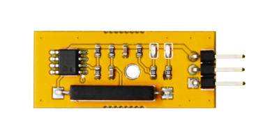
- A reed switch, short for dry reed switch, is a passive electronic switching component with contacts, featuring a simple structure, small size, and easy control. Its casing is typically a sealed glass tube containing two iron-made elastic reed contacts and filled with an inert gas called rhodium. Normally, the two reeds made of special material inside the glass tube are separated. When a magnetic material approaches the glass tube, under the influence of magnetic field lines, the two reeds inside the tube become magnetized and attract each other, causing the reeds to come into contact and the circuit connected to the contacts to be closed. After the external magnetic force disappears, the two reeds separate due to their inherent elasticity, and the circuit is opened. Therefore, as a circuit switching device that uses magnetic field signals for control, a reed switch can be used as a sensor for counting, limiting positions, etc. (primarily used for making door and window magnetic switches in security systems), and is also widely used in various communication devices. In practical applications, a permanent magnet is usually used to control whether these two metal reeds are connected, hence it is also known as a "magnetron".
- Parameter Description:
- Size: 1535mm
- Mounting Hole: 2.5mm
- Sensor: FRS-16A22SMDH1015
- Sensitivity: 10mm-15mm
- Operating Voltage: 5V
- Switch Contact: Normally Open
- Requires use with a magnet. When a certain magnetic force is sensed, it will be in a conductive state, and the module will output a low level. When there is no magnetic force, it will be in an open state and output a high level.
- Reference Routine: Experiment 18: Magnetron Sensor Experiment

3144E Hall Sensor Module
- The AH31 series Hall sensor is a single-ended digital output Hall integrated circuit excited by a single magnetic pole. The sensor chip incorporates circuit units such as a reverse voltage protector, voltage regulator, temperature compensation circuit, Hall voltage generator, signal amplifier, Schmitt trigger, and open-collector output driver. The excellent voltage regulator and temperature compensation circuit ensure stable operation of the sensor over a wide voltage and temperature range, while the reverse voltage protection circuit prevents damage to the sensor from reverse voltage.
- Parameter Description:
- Size: 1535mm
- Mounting Hole: 2.5mm
- Sensor: AH3144
- Operating Voltage: 5V
- Output Current: ≤50mA
- Reference Routine: Experiment 19: Hall Sensor Experiment

SW-18010P Vibration Sensor Module
- Utilizing a normally open high-sensitivity vibration switch, SW-18010P. The switch is in an open OFF state when stationary. When subjected to external force resulting in corresponding vibration or when the movement speed reaches an appropriate centrifugal (or deviation) force, the conductive pins will momentarily conduct, resulting in a transient ON state. When the external force disappears, the switch reverts to the open OFF state. It can be used for various vibration-triggered applications, burglar alarms, smart cars, electronic building blocks, etc. The sensor is equipped with an M3 mounting hole for easy adjustment of direction and secure installation. It uses a wide-voltage LM393 comparator, providing clean signals, good waveform, and strong driving capability exceeding 15mA, with an adjustable precision potentiometer for sensitivity adjustment.
- Parameter Description:
- Size: 1535mm
- Mounting Hole: 2.5mm
- Sensor: SW-18010P
- Operating Voltage: 3.3V - 5V
- Conduction Time: Approximately 2ms
- Output Level: Digital
- Reference Routine: Experiment 20: SW-18010P Vibration Sensor Experiment

SW-520D Tilt Switch Module
- The SW-520 is a dual-ball, one-way tilt-sensing trigger switch.
- When the product is tilted towards the cover end at an angle greater than 10 degrees, the product is in the ON (or OFF) state; when the product's horizontal position changes and the triggering end (gold-plated pin end) is lower than horizontal with a larger tilt angle of 10 degrees, the product is in the closed (or ON) state.
- When the switch is tilted in parallel with the pin direction and the tilt angle at the end of the triggering pin is less than 45 degrees, the switch is in the open state; when the tilt angle at the end of the triggering pin is greater than 45 degrees, the switch is in the closed and connected state.
- Parameter Description:
- Size: 1535mm
- Mounting Hole: 2.5mm
- Sensor: SW-520D
- Operating Voltage: 5V
- Current: <20mA
- Conduction Time: 2 milliseconds
- Closed Circuit Resistance: <10mΩ
- Open Circuit Resistance: >10MΩ
- Reference Routine: Experiment 21: SW-520D Angle Tilt Sensor Experiment

Special Sensors
Grayscale Sensor Module
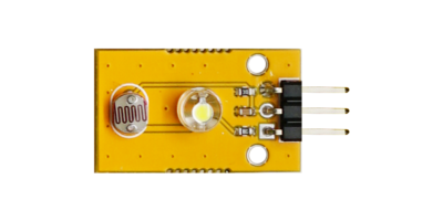
- The grayscale sensor includes a white high-brightness light-emitting diode (LED) and a photoresistor. Due to the different light reflected from paper of varying grayscale when illuminated by the LED, the photoresistor receives this reflected light and its resistance changes based on the intensity of the light, thereby enabling grayscale value measurement. This light and grayscale sensor, developed based on the photoelectric effect principle of semiconductors, primarily uses a phototransistor as its main component. Within an effective detection distance, the LED emits white light onto the detection surface, which reflects some of the light back. The resistance of the phototransistor decreases as the light intensity increases. By connecting it in series with a resistor and outputting the voltage division value of the resistor, the changing light signal can be converted into a changing electrical signal and output through an analog port. The LED on the board can be used for debugging. For example, by shining the LED light on materials of different colors and observing the range of values read by the optical sensor, a color recognizer or line-following robot can be created.
- Parameter Description:
- Size: 1525mm
- Mounting Hole: 2mm
- Sensor: GL5516
- Operating Voltage: 3.3V or 5V
- Operating Current: < 20mA
- Operating Temperature Range: -10℃ to +70℃
- Detection Resolution: 10%
- Interface Type: Analog Signal Output
- Reference Routine: Experiment Twenty-Two: Grayscale Sensor Experiment

TTP223 Touch Switch Module
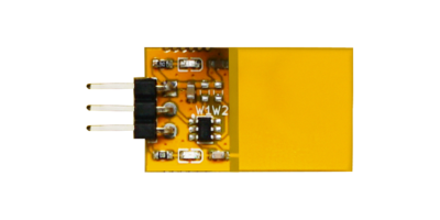
- The momentary capacitive touch switch module is a capacitive momentary touch switch module based on the touch IC (TTP223). In its normal state, the module outputs a low level and operates in low-power mode. When a finger touches the corresponding position, the module outputs a high level and switches to fast mode. If no touch is detected for 12 seconds, the module switches back to low-power mode. The module can be mounted on the surface of non-metallic materials (such as glass) when in use. It has the advantages of small size, long lifespan, and stable performance.
- Parameter Description:
- Size: 1525mm
- Sensor: TTP223
- Operating Voltage: 5V.
- The module has an automatic calibration function. When no keys are touched, the system will recalibrate, with a recalibration period of approximately 4.0 seconds.
- After powering on, a stabilization period of approximately 0.5 seconds is required. During this time, do not touch the keys, as all functions are disabled.
- The output mode can be selected via the W1 and W2 ports
- Direct mode or trigger mode can be selected via W1
- High level active or low level active can be selected via W2
- Reference Routine: Experiment Twenty-Three: TTP223 Capacitive Touch Experiment

Ultrasonic Distance Sensor Module
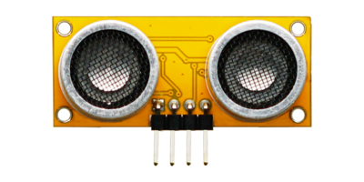
- The ultrasonic module primarily consists of two general-purpose piezoelectric ceramic ultrasonic sensors, along with peripheral signal processing circuits. Specifically, one of the piezoelectric ceramic ultrasonic sensors is used to emit ultrasonic signals, while the other is used to receive the reflected ultrasonic signals. Since both the emitted and received signals are relatively weak, peripheral signal amplifiers are required to increase the power of the emitted signals and amplify the reflected signals, ensuring more stable signal transmission to the microcontroller. Ultrasonic modules are commonly used in applications such as robot obstacle avoidance, object ranging, liquid level detection, public security, parking lot detection, and other scenarios.
- Parameter Description:
- Dimensions: 1842mm
- Mounting Hole: 2mm
- Control Chip: RCWL-9610A
- Operating Voltage: DC 2.8-5V
- Output Ports: GPIO/UART/IIC/1-Wire
- Output Signal: TTL level, proportional to the range
- Operating Current: 2.2mA
- Operating Frequency: 40KHz
- Maximum Measurement Distance: 2cm - 600cm
- Measurement Angle: 15 degrees
- Measurement Accuracy: 0.1cm + 2%
- Measurement Cycle (GPIO/1-Wire): 50ms
- Measurement Cycle (UART/IIC): 100ms
- Reference Example: Experiment 24: Ultrasonic Sensor Experiment

Sound Sensor Module
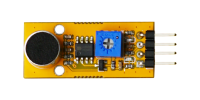
- The sound sensor can be used to receive sound waves and display the vibration image of sound, but it cannot measure the intensity of noise. The sound sensor is equipped with a capacitor electret microphone that is sensitive to sound. Sound waves cause the electret diaphragm inside the microphone to vibrate, leading to changes in capacitance, which in turn generates a corresponding tiny voltage. This voltage is then converted into a 0-5V voltage, undergoes A/D conversion, and is accepted by the data collector before being transmitted to the computer. This sound sensor can detect the sound intensity of the surrounding environment, recognize the loudness of the sound, and output in the form of analog signals, providing real-time output of the microphone's voltage signal, with the analog output varying according to the sound intensity.
- Parameter Description:
- Dimensions: 1535mm
- Mounting Hole: 2.5mm
- Sensor: GMI9767P-52DB
- Operating Voltage: 5V
- Microphone Sensitivity: 52dB
- Frequency Range: 50Hz ~ 20KHz
- Reference Example: Experiment 25: Sound Sensor Experiment

MQ-2 Gas Sensor Module
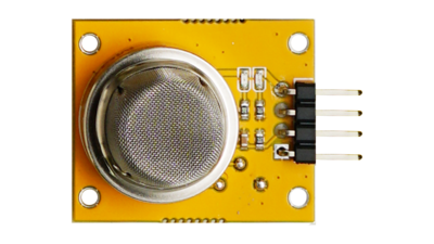
- The MQ-2 gas sensor probe utilizes tin dioxide (SnO2) as the gas-sensitive material, which has a low conductivity in clean air. When the sensor is exposed to an environment containing combustible gases, its conductivity increases with the concentration of the combustible gas in the air. A simple circuit can be used to convert the change in conductivity into an output signal corresponding to the gas concentration. The gas sensor exhibits high sensitivity to liquefied gas, propane, and hydrogen, and is also ideal for detecting natural gas and other combustible vapors. This sensor can detect a variety of combustible gases and is a low-cost sensor suitable for multiple applications.
- Parameter Description:
- Dimensions: 2530mm
- Mounting Hole: 2mm
- Sensor: MQ-2
- Measured Gases: Combustible gases, smoke
- Detection Concentration: 300~10000ppm (combustible gases)
- Operating Voltage: DC5V
- Sensitivity (s): Rs(in air)/Rs(1000ppm isobutane) ≥5
- Output Voltage (Vs): 2.5V~4.0V
- Concentration Slope (a): ≤0.6 (R3000ppm/R1000ppm C3H8)
- Standard Operating Temperature: 20℃ ± 2℃
- Standard Operating Humidity: 65% ± 5%
- Preheating Time: No less than 48 hours
- Reference Example: Experiment 26: MQ-2 Smoke Sensor Experiment

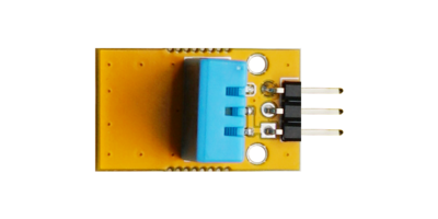
Liquid Level Sensor Module
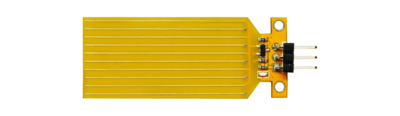
- The Water Sensor (liquid level sensor) is a simple, easy-to-use, compact, and cost-effective sensor for detecting and recognizing water levels or water droplets. It measures the amount of water droplets or water volume by utilizing a series of exposed parallel conductive traces to determine the water level. It effortlessly converts water volume into an analog signal, and the output analog value can be directly applied by functions in a program to achieve the function of water level alarm. Low power consumption and high sensitivity are its other notable features. When used with an Arduino controller, it can be directly plugged into a sensor expansion board for application, yielding even more pronounced results.
- Parameter Description:
- Dimensions: 2051mm
- Mounting Hole: 2mm
- Operating Voltage: DC3-5V
- Operating Current: Less than 20mA
- Sensor Type: Analog
- Detection Area: 40mm x 20mm (maximum detection depth of 4cm)

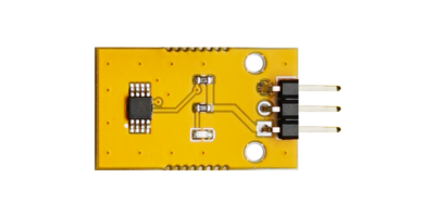
Soil Moisture Sensor Module
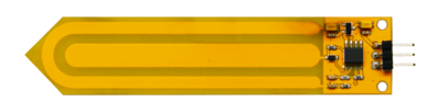
- A capacitive humidity sensor is a sensor that measures humidity based on the principle that the capacitance of a humidity-sensitive element changes with humidity. This type of humidity-sensitive element is actually a thin-film capacitor where the dielectric constant of a hygroscopic electrolyte material changes with humidity. The humidity-sensitive materials include polyamide resin, acyl cellulose, and metal oxides such as AL2O3.
- The capacitive soil moisture sensor differs from most resistive sensors on the market by using capacitive sensing principles to detect soil moisture. This avoids the issue of resistive sensors being highly susceptible to corrosion, significantly extending its operational lifespan. The sensor is equipped with a voltage regulator chip, supporting a wide operating voltage range of 3.3~5.5V, meaning it can function normally even on a 3.3V Arduino main control board.
- Parameter Description:
- Dimensions: 2095mm
- Mounting Hole: 2mm
- Operating Voltage: DC 3.3-5.5V
- Output Voltage: DC 0-3.0V
- Output Signal: Analog signal
- Reference Example: Experiment 28: Soil Moisture Sensor Experiment

Display Module
8x8 MAX7219 Dot Matrix Module
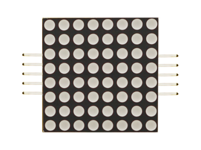
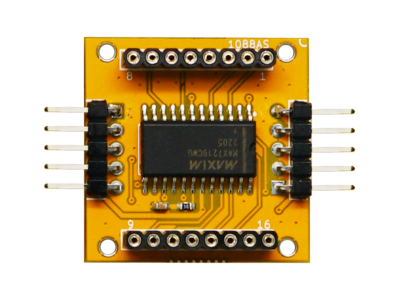
- The MAX7219 is an integrated serial input/output common-cathode display driver that connects a microprocessor to an 8-digit 7-segment LED display, or it can be connected to a bar graph display or 64 individual LEDs. It includes an on-chip B-type BCD encoder, multiplex scan circuitry, segment drivers, and an 8x8 static RAM for storing each data point. Only one external resistor is needed to set the segment current for each LED. A convenient 4-wire serial interface can be connected to a general-purpose microprocessor. Each data point can be addressed without rewriting the entire display during updates. The MAX7219 also allows the user to select encoded or non-encoded data for each point. The device includes a low-power shutdown mode of 150μA, analog and digital brightness control, a scan limit register that allows the user to display 1-8 digits, and a test mode that illuminates all LEDs.
- Parameter Description:
- Dimensions: 3030mm
- Control Chip: MAX7219CWG
- Operating Voltage: 5V
- Control Interface: Serial Control
- Dot Matrix Specification: 8*8 Common-Cathode
- Supports Multiple Module Cascading
- Reference Example: Experiment 29: MAX7219 Dot Matrix Experiment


Digital Tube Display Module(74HC595)
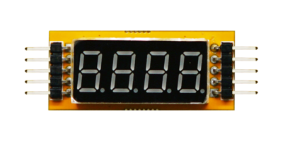
- A digital tube, also known as a nixie tube, is an electronic device that can display numbers and other information. It consists of an anode made of a metal mesh and multiple cathodes inside a glass tube. Most of the cathode shapes represent numbers. The tube is filled with low-pressure gas, usually neon with some mercury and/or argon. By energizing a specific cathode, the digital tube emits a colored light depending on the gas inside.
- Parameter Description:
- Dimensions: 1842mm
- Mounting Hole: 2mm
- Control Chip: 74HC595
- Digital Tube Specification: 0.36-inch, 4-digit, Common-Cathode
- Reference Example: Experiment 30: 4-Digit Serial Digital Tube Experiment

LCD1602
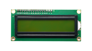
- The 1602 character LCD display module is specifically designed to display letters, numbers, symbols, and other information in a dot-matrix format. It supports 4-bit and 8-bit data transfer modes. It provides a 5x7 dot-matrix plus cursor display mode. It includes a display data RAM (DDRAM), a character generator ROM (CGROM), and a character generator RAM (CGRAM), allowing users to store custom character patterns for up to 8 5x8 dot-matrix graphics characters using CGRAM. It offers a rich set of commands for clearing the display, resetting the cursor to the home position, turning the display on/off, turning the cursor on/off, blinking the displayed characters, shifting the cursor, and shifting the display. It includes an internal power-on reset circuit that automatically initializes the module to its default display state when power is applied.
- Parameter Description:
- Power Supply Voltage: 4.5V-5.5V (5V optimal)
- Screen: Yellow-green
- Display Capacity: 16x2 characters
- Data Transfer: 4-bit or 8-bit parallel
- Interface Pins: 16
- Operating Current (without backlight): 0.9mA-1.7mA
- Operating Current (with backlight): 35mA-40mA
- Driving Voltage: 4.2V-4.8V (4.5V optimal)
- Driving Current: 0.6mA
- Backlight Power Consumption: 170mW-200mW
- Display Duty Cycle: 1/16
- Driving Bias: 1/5
- Operating Temperature: -20℃ to 70℃
- Storage Temperature: -30℃ to 80℃
- Visible Area: 76mm x 25.2mm
- External Dimensions: 98mm x 60mm x 13.5mm
- Reference Example: Experiment 31: LCD1602 Parallel Control Experiment

LCD1602 IIC Module
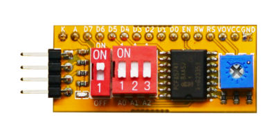
- The module uses the PCF8574, which enables most MCUs to expand their remote I/O ports through two bidirectional buses (I2C). The device includes an 8-bit quasi-bidirectional port and an I2C bus interface. The PCF8574 consumes very little current, and its parallel output latch has high current drive capability, allowing it to directly drive LEDs. It also features an interrupt line (INT open-drain output) that can be connected to the MCU's interrupt logic. By sending an interrupt signal through INT, the remote I2C port can notify the MCU of incoming data without requiring I2C bus communication.
- Parameter Description:
- Dimensions: 1842mm
- Control Chip: PCF8574
- Power Supply Voltage: 2.5V-5.5V
- Communication Interface: I2C Interface
- Includes Backlight Control Button and Address Selection Button
- Reference Example: Experiment 32: LCD1602 I2C Display Experiment

Motor
ULN2003 Driver Board
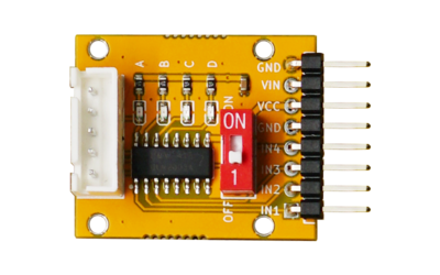
- The ULN2003A is a commonly used integrated high-voltage and high-current output device, belonging to an NPN transistor array. It consists of eight independent NPN transistors, with the base of each transistor connected to a common pin (COM) and the collector connected to external loads through open-collector pins.
- Parameter Description:
- Dimensions: 2530mm
- Mounting Hole: 2mm
- Control Chip: ULN2003A
- Operating Voltage: 5V
- Input Current: 1.0mA ~ 2.7mA
- Output Current per Channel: 500mA
- Reference Example: Experiment 33: DC Motor Driving Experiment

Miniature DC Motor
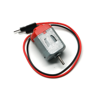
- The DC motor is the most common type of motor. A DC motor typically has only two leads, a positive and a negative. If these two leads are directly connected to a battery, the motor will rotate. If the leads are switched, the motor will rotate in the opposite direction.
- Do not drive the motor directly from the Arduino board pins. This may damage the circuit board. Use a driver circuit or IC.
- Reference Example: Experiment 34: Fan Speed Adjustment Experiment

5-Wire 4-Phase DC Stepper Motor (5V)
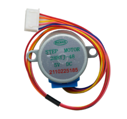
- Reference Example: Experiment 35: Stepper Motor Experiment
