Experiment 9: DHT11 Temperature and Humidity Sensor Experiment
From Diustou Wiki
Revision as of 12:04, 11 February 2025 by Yousimaier17 (talk | contribs)
Data Structure
- The DHT11 digital temperature and humidity sensor adopts a single-bus data format, meaning input and output bidirectional transmission is achieved through a single data pin port. The communication time for one cycle is approximately 4ms, and a complete data packet consists of 5 bytes (40 bits). The data includes both fractional and integer parts, transmitted in the order of high bits first, followed by low bits. The specific format is as follows:
- Data format: 8-bit humidity integer data + 8-bit humidity fractional data + 8-bit temperature integer data + 8-bit temperature fractional data + 8-bit checksum
- Since the resolution of the DHT11 can only be accurate to the whole number, the fractional part is all zeros. The checksum is the sum of the first four bytes of data, used to ensure the accuracy of data transmission.
- Additionally, because the data output by the sensor is unencoded binary data, the temperature, humidity, integer, and fractional parts should be processed separately during data processing.
For example, if the 40-bit data transmitted by the sensor at a certain time is
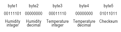 From the above values, it can be derived that:
Humidity = byte1.byte2 = 00111101.00000000 = 61.0%RH
Temperature = byte3.byte4 = 00011110.00000000 = 30.0°C
Checksum = 01011011 = byte1 + byte2 + byte3 + byte4 = 00111101 + 00000000 + 00011110 + 00000000 (take the last 8 bits of the sum result; if equal, the checksum is correct)
From the above values, it can be derived that:
Humidity = byte1.byte2 = 00111101.00000000 = 61.0%RH
Temperature = byte3.byte4 = 00011110.00000000 = 30.0°C
Checksum = 01011011 = byte1 + byte2 + byte3 + byte4 = 00111101 + 00000000 + 00011110 + 00000000 (take the last 8 bits of the sum result; if equal, the checksum is correct)

Control Timing
- The DHT11 communicates with the microcontroller using a single-bus protocol. After the host sends a reset signal, the DHT11 switches from low-power mode to high-speed mode. After the host completes the reset, the DHT11 sends a response signal and pulls the bus high to prepare for data transmission. The user can choose to read part of the data. The DHT11 only triggers a temperature and humidity measurement after receiving a reset signal. If no reset signal is sent by the host, the DHT11 does not actively perform temperature and humidity measurements. When data collection is complete and there is no start signal, the DHT11 automatically switches to low-speed mode.
- The entire communication process can be divided into the following steps:
- 1. DHT11 Initialization - Trigger DHT11 to collect data
- Host sends reset signal
- DHT11 sends response signal
- 2. DHT11 sends collected data
DHT11 Initialization

- Host sends reset signal
- The bus is in a high state when idle. The host pulls the bus low and waits for the DHT11 to respond. The pull-down time must be greater than 18ms to ensure that the DHT11 can detect the reset signal.
- After sending the reset signal, the host pulls the bus high or switches to input mode, with a delay of 20~40us. At this point, the reset signal transmission is complete, and the host waits to receive the response signal from the DHT11.
- DHT11 sends response signal
- After detecting the reset signal, the DHT11 triggers a sampling and pulls the bus low for 80us to indicate the response signal, telling the host that the data is ready.
- After sending the 80us response signal, the DHT11 pulls the bus high for 80us and then starts transmitting data.
Data Transmission
The DHT11 starts transmitting data after pulling the bus high for 80us. Each 1-bit of data starts with a 50us low-level time slot, indicating to the host that a bit of data is being transmitted. The data bit is 0 or 1 depending on the length of the high level. If the response signal detected is high, the DHT11 initialization fails; please check if the wiring is correct. After the last bit of data is transmitted, the DHT11 pulls the bus low for 50us, indicating that data transmission is complete. Subsequently, the bus is pulled high by the pull-up resistor to enter the idle state.
- Data '0' timing
- When the DHT11 sends a 50us low-level time slot and then pulls the bus high, if the high level lasts for 26~28us, it represents data "0".

- Data '1' timing
- When the DHT11 sends a 50us low-level time slot and then pulls the bus high, if the high level lasts for 70us, it represents data "1".

Overall Timing

- The host pulls the bus low for more than 18ms to ensure that the DHT11 can detect the start signal.
- After the host sends the reset signal, it pulls the bus high or switches to input mode, waits for 20-40us, and then reads the response signal from the DHT11.
- When the host detects that the bus is pulled low (the start signal sent by the DHT11), it counts once every 1us until the bus is pulled high, calculating whether the low-level time is 80us. If the response signal read is high, the DHT11 has not responded; please check if the wiring is correct.
- After the host detects that the bus is pulled high, it counts again to detect the high-level time. If the high-level time after detecting the response signal is 80us, it prepares to start receiving data.
- Each bit of data received by the host starts with a 50us low-level time slot, and the length of the high level determines whether the data bit is 0 or 1.
- After the host receives the last bit of data, the DHT11 pulls the bus low for 50us, and then the bus is pulled high by the pull-up resistor to enter the idle state.
- Note:
- In reality, the response time of the DHT11 is not exactly 80us and often has errors. When the response time is between 20~100us, it can be considered a successful response.
- Due to the strict timing requirements of the DHT11, to prevent interrupts from interfering with the bus timing, disable all interrupts before operating the timing and re-enable them after the operation is complete.
- The DHT11 only triggers a temperature and humidity measurement after receiving a reset signal. If no reset signal is sent by the host, the DHT11 does not actively perform temperature and humidity measurements.
Distinguishing Between 0/1 Timing
- The DHT11 sends data "0" and data "1" mainly distinguished by the length of the high level. The high level for data "0" lasts for 26~28us, and the high level for data "1" lasts for 70us. Each bit of data is preceded by a 50us start time slot.
- If a middle value of 40us is taken to distinguish between data "0" and data "1". After the 50us low-level time slot preceding the data bit, the bus is pulled high. At this point, delay for 40us and then check the bus state. If it is high, it indicates that it is in the 70us time slot, so the data is "1". If it is low, it indicates that it is the start time slot for the next bit of data, so the previous bit of data must be "0".
- Due to errors, the data "0" time slot may not be exactly 2628us; it may be shorter or longer. When the data "0" time slot is longer than 2628us, if the delay is too short, it is unable to determine whether it is currently in the data "0" time slot or the data "1" time slot. If the delay is too long, it will miss the start time slot before the next bit of data, causing the subsequent data to be undetected.
Arduino
Experimental Phenomenon
- The serial port outputs the measurement data from the DHT11 sensor.
Circuit Connection

Reference Program
#include <Arduino.h>
#include "DHT11.h"

DHT11 myDHT11(2);

void setup()      //The Arduino initialization code goes here and runs only once at startup
{
  Serial.begin(9600); //Set the communication baud rate to 9600
  Serial.println("Welcome to use!");  //Content to send
  Serial.println("I love DIUSTOU");  //Content to send
}

void loop()     ) //The main part of the Arduino program, which runs the internal code in a loop
{
  myDHT11.DHT11_Read();                //Read temperature and humidity values
  Serial.print("HUMI = ");
  Serial.print(myDHT11.HUMI_Buffer_Int);
  Serial.println(" %RH");

  Serial.print("TMEP = ");
  Serial.print(myDHT11.TEM_Buffer_Int);
  Serial.println(" C");
  delay(1000);       //Delay for 1s }
Raspberry Pi
Circuit Connection
Program Execution
Python
- Install the gpiozero library
- You can install the library using the following commands:
sudo apt update
sudo apt install python3-gpiozero
- For other systems on the Raspberry Pi, you can install the library with the following commands:
sudo pip3 install gpiozero
- Run the following command to view the GPIO pin definitions on the Raspberry Pi:
pinout
- Install the adafruit-circuitpython-dht library
sudo pip3 install adafruit-circuitpython-dht
sudo apt-get install libgpiod2
- Download the Raspberry Pi reference example, unzip the file, copy it to your home directory, and run it:
cd raspberrypi/9/python_gpiozero
python sensor.py
- You should now see the Raspberry Pi running the DHT11 program correctly, printing the detected temperature and humidity values. To exit, press ctrl+C.
- For more commands, please refer to the gpiozero documentation