Experiment 15: Infrared Tracking Sensor Experiment
From Diustou Wiki
Revision as of 15:26, 12 February 2025 by Yousimaier17 (talk | contribs) (Created page with "*Basic Experiment Kits For Arduino *Basic Experiment Kits For Raspberry Pi == Arduino == === Experimental Phenomenon === * Print the measured voltage value through the...")
Contents
Arduino
Experimental Phenomenon
- Print the measured voltage value through the serial port.
- When the obstacle distance is below the threshold, the onboard LED lights up.
- When the obstacle distance is above the threshold, the onboard LED turns off.
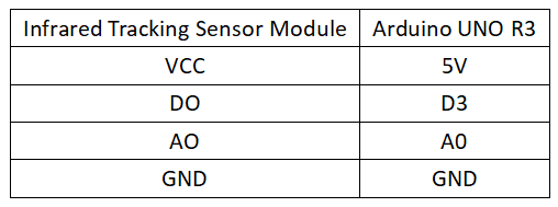
Circuit Connection
Reference Program
#define SEN1 A0
#define SEN2 3
#define LED 13

int value1 = 0;
int value2 = 0;

void setup()
{
  pinMode(LED,OUTPUT);
  pinMode(SEN1,INPUT);
  pinMode(SEN2,INPUT);
  Serial.begin(9600);        //Baud rate 9600
}

void loop()
{
  value1 = analogRead(SEN1);   //Read AD value
  value2 = digitalRead(SEN2);
  Serial.print("AD = ");
  Serial.println(value1);
  Serial.print("Value = ");
  Serial.print(value1*5.0/1025);
  Serial.println("V");
  if(value2 == LOW)               //ADBuffer value is less than the set value, equivalent to temperature being greater than the set value
  {
    digitalWrite(LED,HIGH);   //Turn on LED
  }
  else
  {
    digitalWrite(LED,LOW);    //Turn off LED
  }
  delay(500);         //Delay 500ms
}
Raspberry Pi
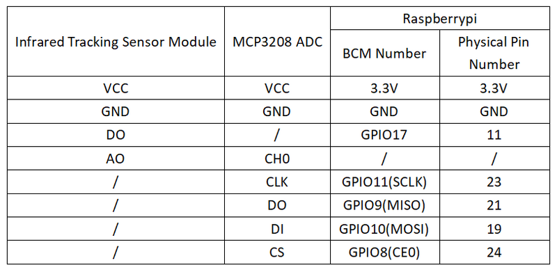
Circuit Connection
Program Execution
Python
- Install the gpiozero library
- You can use the following command to install the library:
sudo apt update
sudo apt install python3-gpiozero
- For other systems on the Raspberry Pi, you can use the following command to install the library:
sudo pip3 install gpiozero
- Run the following command to view the GPIO pin definitions on the Raspberry Pi:
pinout
- Enable the SPI interface
sudo raspi-config
Select Interfaces oOptions -> SPI -> “Would you like the SPI interface to be enabled? ”Select Yes -> “The SPI interface is enabled” Select Yes -> Select finish
- Shut down the Raspberry Pi. With the power off, connect the corresponding modules to the circuit according to the provided circuit connection, and then start the Raspberry Pi.
- Download the Raspberry Pi reference example, unzip the file, copy it to the user directory, and run it:
cd raspberrypi/15/python_gpiozero
python sensor.py
- At this point, you can see the Raspberry Pi running the program correctly. To exit, press ctrl+C.
- Command description: gpiozero.Button(pin, pull_up, active_state, bounce_time, hold_time, hold_repeat)
- Button inherits from DigitalInputDevice and represents a simple button or switch. One end of the button is connected to ground, and the other end is connected to any GPIO pin; or one end of the button is connected to the 3V3 pin, and the other end is connected to any GPIO pin, and then set pull_up to False in the Button's initialization constructor.
- Main parameters:
- pin: GPIO pin number;
- pull_up: Internal pull-up/pull-down resistor setting,
- When set to True (default), the GPIO pin is pulled high, and the other end of the button should be connected to ground.
- When set to False, the GPIO pin is pulled low, and the other end of the button should be connected to 3V3.
- When set to None, the GPIO pin is floating, and gpiozero cannot guess the active state, so active_state must be set.
- active_state:
- When set to True, the software pin state is also "high" when the hardware pin state is "high".
- When set to False, the input polarity is reversed, and the software pin state is "low" when the hardware pin state is "high".
- When pull_up is set to None, use this parameter to set the unknown pin active state.
- When pull_up is set to True or False, the pin's active state is automatically assigned.
- bounce_time: Software debounce time. Generally, a switch has unstable signals within about 20ms, known as "switch bounce".
- When set to None, no software debounce compensation is performed; otherwise, this parameter is the length of time (in seconds) that the component ignores after the initial change, with a default of 1s.
- hold_time: The time after pressing the button until when_held is triggered, in seconds.
- hold_repeat:
- If True, when_held will continue to be triggered every hold_time as long as the button remains pressed.
- If False, when_held will only be triggered once.
- For more commands, please refer to the gpiozero documentation

