Experiment 22: Gray Scale Sensor Experiment
From Diustou Wiki
Revision as of 15:56, 12 February 2025 by Yousimaier17 (talk | contribs) (Created page with "*Basic Experiment Kits For Arduino *Basic Experiment Kits For Raspberry Pi == Arduino == === Experimental Phenomenon === * Print the digital value corresponding to the...")
Contents
Arduino
Experimental Phenomenon
- Print the digital value corresponding to the grayscale value measured by the module via serial port.
- When the grayscale exceeds the threshold, the onboard LED turns on.
- When the grayscale is below the threshold, the onboard LED turns off.
Programming Principle
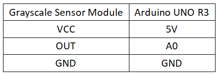
- The grayscale sensor has three pins: Vcc for power, GND for ground, and OUT for signal. It can be directly connected to an analog interface of the Arduino controller, such as analog pin A0. After powering on the Arduino, the sensor's white high-brightness LED lights up. Place the sensor on paper with different grayscale levels, and use the Arduino controller's built-in AD conversion to read the data. Then, print the measured analog value through the serial port.
- The light-emitting diode (LED) is connected in series with a 1K resistor. The LED serves as a light source, illuminating the object being detected, while the 1K resistor limits the current. The photoresistor is connected in series with a 10K resistor. The photoresistor has the characteristic of decreasing resistance with increasing light intensity. When the LED shines on a white object, the white object reflects all the light, resulting in strong brightness, low photoresistor resistance, small voltage division, and a high output voltage at the OUT pin. When the LED shines on a black object, the black object absorbs all the light, resulting in weak brightness, high photoresistor resistance, large voltage division, and a low output voltage at the OUT pin.
Circuit Connection
Reference Program
int Led = 13;
int buttonpin = A0;
int val;

void setup()
{
  Serial.begin(9600);
  pinMode(Led, OUTPUT);
  pinMode(buttonpin, INPUT);
}

void loop()
{
  val = analogRead(buttonpin);
  Serial.println(val,DEC);
  if (val < 400)
  {
    digitalWrite(Led, HIGH);
  }
  else
  {
    digitalWrite(Led, LOW);
  }
}
Raspberry Pi
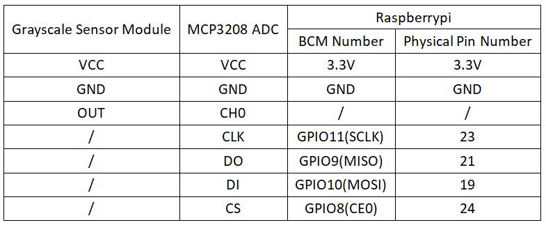
Circuit Connection
Program Execution
Python
- Install the gpiozero library
- You can use the following command to install the library:
sudo apt update
sudo apt install python3-gpiozero
- For other systems on the Raspberry Pi, you can use the following command to install the library:
sudo pip3 install gpiozero
- Run the following command to view the GPIO pin definitions on the Raspberry Pi:
pinout
- Enable the SPI interface
sudo raspi-config
Select Interfaces oOptions -> SPI -> “Would you like the SPI interface to be enabled? ”Select Yes -> “The SPI interface is enabled” Select Yes -> Select finish
- Shut down the Raspberry Pi. With the power off, connect the corresponding modules to the circuit according to the provided circuit connection, and then start the Raspberry Pi.
- Download the Raspberry Pi reference example, unzip the file, copy it to the user directory, and run it:
cd /home/pi/raspberrypi/22/python_gpiozero
python sensor.py
- At this point, you can see the Raspberry Pi continuously printing the voltage values output by the module. To exit, press ctrl+C.
- For more commands, please refer to the gpiozero documentation

