Experiment 23: TTP223 Capacitive Touch Experiment
From Diustou Wiki
Revision as of 15:56, 12 February 2025 by Yousimaier17 (talk | contribs) (Created page with "*Basic Experiment Kits For Arduino *Basic Experiment Kits For Raspberry Pi == Parameter Description == *Output mode can be selected via ports W1 and W2 **Pin W1 provid...")
Contents
Parameter Description
- Output mode can be selected via ports W1 and W2
- Pin W1 provides selection between direct mode and trigger mode
- Pin W2 provides selection between fast mode and low-power mode
- W1=0, W2=0: Output is in direct mode, high level active
- W1=0, W2=1: Output is in direct mode, low level active
- W1=1, W2=0: Output is in trigger mode, power-on state is 0
- W1=1, W2=1: Output is in trigger mode, power-on state is 1
Arduino
Experimental Phenomenon
- When the button is pressed, the onboard LED lights up.
- When the button is released, the onboard LED turns off.
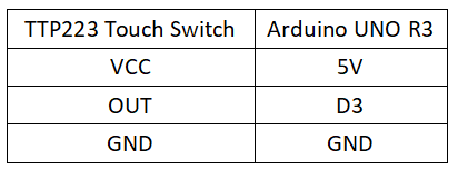
Circuit Connection
Reference Program
#define SEN 3
#define LED 13

int value = 0;

void setup()
{
  pinMode(LED,OUTPUT);
  pinMode(SEN,INPUT);
  Serial.begin(9600);       //Baud rate 9600
}

void loop()
{
  value = digitalRead(SEN);
  if(value == HIGH)               //ADBuffer value is less than the set value, equivalent to temperature being greater than the set value
  {
digitalWrite(LED,HIGH);  //Turn on LED
    Serial.println("TTP223 has been pressed");
  }
  else
  {
   digitalWrite(LED,LOW);    //Turn off LED
  }
  delay(500);        //Delay 500ms
}
Raspberry Pi
Circuit Connection
Program Execution
Python
- Install the gpiozero library
- You can use the following command to install the library:
sudo apt update
sudo apt install python3-gpiozero
- For other systems on the Raspberry Pi, you can use the following command to install the library:
sudo pip3 install gpiozero
- Run the following command to view the GPIO pin definitions on the Raspberry Pi:
pinout
- Download the Raspberry Pi reference example, unzip the file, copy it to the user directory, and run it:
cd raspberrypi/23/python_gpiozero
python sensor.py
- At this point, you can see that the Raspberry Pi is running the program correctly. To exit, press ctrl+C.
- Command description: gpiozero.Button(pin, pull_up, active_state, bounce_time, hold_time, hold_repeat)
- Button inherits from DigitalInputDevice and represents a simple button or switch. One end of the button is connected to ground, and the other end is connected to any GPIO pin; or one end of the button is connected to the 3V3 pin, and the other end is connected to any GPIO pin, and then set pull_up to False in the Button's initialization constructor.
- Main parameters:
- pin: GPIO pin number;
- pull_up: Internal pull-up/pull-down resistor setting,
- When set to True (default), the GPIO pin is pulled high, and the other end of the button needs to be connected to ground.
- When set to False, the GPIO pin is pulled low, and the other end of the button needs to be connected to 3V3.
- When set to None, the GPIO pin is floating, and gpiozero cannot guess the active state, so active_state must be set.
- active_state:
- When set to True, the software pin state is also "high" when the hardware pin state is "high".
- When set to False, the input polarity is reversed, and when the hardware pin state is "high", the software pin state is "low".
- When pull_up is set to None, use this parameter to set the unknown pin active state.
- When pull_up is set to True or False, the pin's active state is automatically assigned.
- bounce_time: Software debounce time. Generally, the signal of a switch is unstable within about 20ms, known as "switch bounce".
- When set to None, software debounce compensation is not performed; otherwise, this parameter is the length of time (in seconds) that the component ignores after the initial change, with a default of 1s.
- hold_time: The time after pressing the button until when_held is triggered, in seconds.
- hold_repeat:
- If True, as long as the button remains pressed, when_held will continue to be triggered every hold_time interval.
- If False, when_held will only be triggered once.
- Command description: gpiozero.LED(pin, pwm, active_high, initial_value)
- Main parameters:
- pin: GPIO pin number,
- active_high:
- When set to True (default), connect the negative lead of the LED to GND and the other end to the GPIO pin.
- When set to False, connect the negative lead of the LED to the GPIO pin and the other end to the 3.3V pin.
- initial_value:
- If False (default), the LED initial state is off.
- If None, the LED pin is in an unstable state.
- If True, the LED initial state is on.
- Main parameters:
- For more commands, please refer to the gpiozero documentation

