Experiment 29: MAX7219 LED Matrix Experiment
From Diustou Wiki
Revision as of 17:31, 12 February 2025 by Yousimaier17 (talk | contribs) (Created page with "*Basic Experiment Kits For Arduino *Basic Experiment Kits For Raspberry Pi == Arduino == === Experimental Phenomenon === * The module cyclically displays patterns when...")
Contents
Arduino
Experimental Phenomenon
- The module cyclically displays patterns when powered on.
Precautions
- When wiring, pay attention to the direction. The left side pin header is the input terminal (1088AS silkscreen is on the top of the PCB board).
- Be mindful of the LED orientation. If the display is abnormal, please reverse the insertion direction.
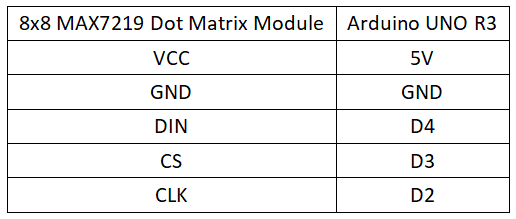
Circuit Connection
Reference Program
#include "LedControl.h"
int DIN = 4;
int CS =  3;
int CLK = 2;

LedControl lc=LedControl(DIN,CLK,CS,0);

void setup(){
 lc.shutdown(0,false);
 lc.setIntensity(0,15);      //Adjust the brightness maximum is 15
 lc.clearDisplay(0);
}

void loop(){

    //Facial Expression
    byte smile[8]=   {0x3C,0x42,0xA5,0x81,0xA5,0x99,0x42,0x3C};
    byte neutral[8]= {0x3C,0x42,0xA5,0x81,0xBD,0x81,0x42,0x3C};
    byte sad[8]=   {0x3C,0x42,0xA5,0x81,0x99,0xA5,0x42,0x3C};

    //Arrow
    byte arrow_up[8]= {0x18,0x3C,0x7E,0xFF,0x18,0x18,0x18,0x18};
    byte arrow_down[8]= {0x18,0x18,0x18,0x18,0xFF,0x7E,0x3C,0x18};


    //Alternate Pattern
    byte d1[8]= {0xAA,0x55,0xAA,0x55,0xAA,0x55,0xAA,0x55};
    byte d2[8]= {0x55,0xAA,0x55,0xAA,0x55,0xAA,0x55,0xAA};

    //Moving car
    byte b1[8]= {0x00,0x00,0x00,0x00,0x18,0x3C,0x18,0x3C};//8x8 LED dot matrix pattern generated by software
    byte b2[8]= {0x00,0x00,0x00,0x18,0x3C,0x18,0x3C,0x00};
    byte b3[8]= {0x00,0x00,0x18,0x3C,0x18,0x3C,0x00,0x00};
    byte b4[8]= {0x00,0x18,0x3C,0x18,0x3C,0x00,0x00,0x00};
    byte b5[8]= {0x18,0x3C,0x18,0x3C,0x00,0x00,0x00,0x00};
    byte b6[8]= {0x3C,0x18,0x3C,0x00,0x00,0x00,0x00,0x18};
    byte b7[8]= {0x18,0x3C,0x00,0x00,0x00,0x00,0x18,0x3C};
    byte b8[8]= {0x3C,0x00,0x00,0x00,0x00,0x18,0x3C,0x18};


//Moving car
    printByte(b1);
    delay(50);
    printByte(b2);
    delay(50);
    printByte(b3);
    delay(50);
    printByte(b4);
    delay(50);
    printByte(b5);
    delay(50);
    printByte(b6);
    delay(50);
    printByte(b7);
    delay(50);
    printByte(b8);
    delay(50);

//alternate pattern
    printByte(d1);
    delay(100);

    printByte(d2);
    delay(100);

//Arrow
    printByte(arrow_up);
    delay(2000);

    printByte(arrow_down);
    delay(2000);


//Facial Expression
    printByte(smile);

    delay(1000);

    printByte(neutral);

    delay(1000);

    printByte(sad);

    delay(1000);


}

void printByte(byte character [])
{
  int i = 0;
  for(i=0;i<8;i++)
  {
    lc.setRow(0,i,character[i]);
  }
}
Raspberry Pi
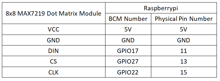
Circuit Connection
Program Execution
Python
- Install the gpiozero library
- You can use the following command to install the library:
sudo apt update
sudo apt install python3-gpiozero
- For other systems on the Raspberry Pi, you can use the following command to install the library:
sudo pip3 install gpiozero
- Run the following command to view the GPIO pin definitions on the Raspberry Pi:
pinout
- Download the Raspberry Pi reference example, unzip the file, copy it to the user directory, and run it:
cd raspberrypi/29/python_gpiozero
python MAX7219.py
- At this point, you can see the Raspberry Pi running the program correctly. To exit, press ctrl+C.
- Command explanation: gpiozero.OutputDevice(pin, active_high, initial_value)
- Main parameters:
- pin: GPIO pin number
- active_high: Internal pull-up/pull-down resistor setting
- When set to True (default), on() sets the pin to High, and off() sets the pin to LOW.
- When set to False, on() sets the pin to LOW, and off() sets the pin to High.
- initial_value:
- If False (default), all LEDs are initially off.
- If None, the initial state of all LEDs is unstable.
- If True, all LEDs are initially on.
- Main parameters:
- For more commands, please refer to the gpiozero documentation

