Experiment 30: 4-Digit Serial Seven-Segment Display Experiment
Contents
Display Principle
Internal Structure
A digital tube is an electronic device that can display numbers and other information, which can be regarded as a composition of multiple light-emitting diodes (LEDs). Digital tubes can be classified in multiple ways, as follows:
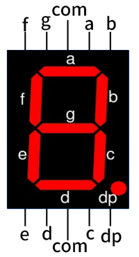
- According to the number of segments, digital tubes can be divided into seven-segment and eight-segment digital tubes. a, b, c, d, e, f, g represent the display segments of a seven-segment digital tube, while an eight-segment digital tube has one more LED unit than a seven-segment one (an additional decimal point dp display).
- Based on how many "8"s the digital tube can display, it can be categorized into 1-digit, 2-digit, 3-digit, 4-digit, 5-digit, 6-digit, 7-digit, etc.
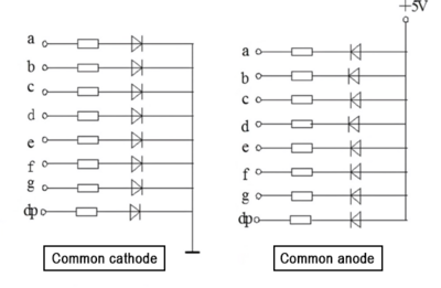
- According to the connection method of the LED units, digital tubes can be classified into common-anode and common-cathode digital tubes. A common-anode digital tube refers to one where all the anodes of the LEDs are connected together to form a common anode (COM); a common-cathode digital tube refers to one where all the cathodes of the LEDs are connected together to form a common cathode (COM).
Display Principle
To make a digital tube display numbers, two conditions need to be met: first, apply an appropriate power supply to the common terminal (usually, each LED segment also needs to be connected in series with an appropriate resistor to limit the current and protect the digital tube); second, connect the (a, b, c, d, e, f, g, dp) terminals to low or high levels. Only then can it display. Therefore, in practical applications, the wiring methods for common-cathode and common-anode digital tubes are slightly different, as follows:
- Common-anode digital tube: Connect the common terminal COM to +5V. When the cathode of an LED segment is at a low level, the corresponding segment lights up; when it is at a high level, the corresponding segment does not light up.
- Common-cathode digital tube: Connect the common terminal COM to ground (GND). When the anode of an LED segment is at a high level, the corresponding segment lights up; when it is at a low level, the corresponding segment does not light up.
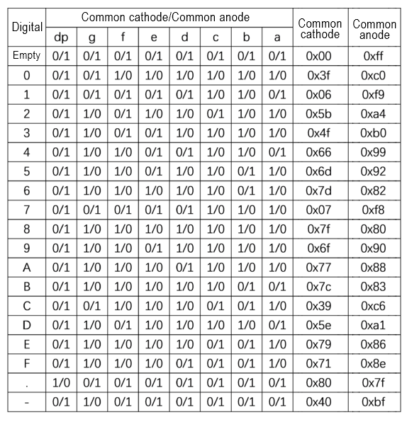
Truth Table
Driving Methods
There are two driving methods for LED digital tubes: static driving and dynamic display. Note: Bit selection refers to selecting a specific digit in a multi-digit digital tube; segment selection refers to selecting a specific segment within a digital tube.
1. Static Driving Method
Static driving is also known as DC driving. It means that each segment of the digital tube needs to be connected to an 8-bit data line to maintain the display of the character code. These 8-bit data lines can be driven through the I/O ports of a microcontroller or using devices such as BCD-to-decimal converters. Once a character code is input, the display pattern remains until a new character code is input. The advantages of static driving are simple programming and high display brightness. The disadvantage is that it occupies many I/O ports. When using a microcontroller to control the display of n digital tubes, the number of I/O ports required is 8*n. Therefore, drivers are often added in practical applications to drive the display, which increases the complexity of the hardware circuit.
2. Dynamic Display Method
Dynamic driving refers to connecting all the segment selection lines of the digital tubes in parallel and controlling which digit is active through the bit selection lines. For example, when the microcontroller outputs a character code, all digital tubes receive the same code. Then, by turning on the bit selection for the digit that needs to be displayed, that digit can display the character, while the other digits that are not selected will not light up. The selection of lit digits adopts dynamic scanning display. Dynamic scanning display means sequentially sending character codes and corresponding bit selections to each digit, utilizing the afterglow of the LEDs and the persistence of vision of the human eye. As long as the scanning speed is fast enough, it will give the illusion that stable characters are being displayed, and all selected digits are displaying normally. Compared with static driving, dynamic driving can save a large number of I/O ports and has lower power consumption. However, the brightness of dynamic display is slightly worse than that of static display, so when selecting the current-limiting resistors, they should be slightly smaller than those used in static display circuits.
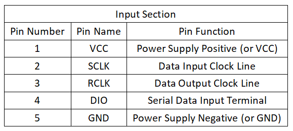
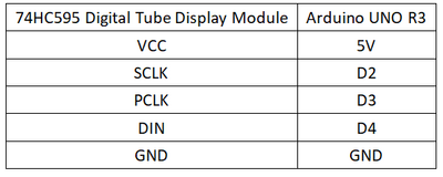
Pin Description
Arduino
Experimental Phenomenon
- The digital tube powers on, and displays numbers 0-9 in a 4-digit cycle.
Circuit Connection
Reference Program
int SCLK=2;
int PCLK=3;
int DO=4;
unsigned char num[]={0xC0, //"0"
                     0xF9, //"1"
                     0xA4, //"2"
                     0xB0, //"3"
                     0x99, //"4"
                     0x92, //"5"
                     0x82, //"6"
                     0xF8, //"7"
                     0x80, //"8"
                     0x90  //"9"
};
void setup()
{
  pinMode(PCLK,OUTPUT);
  pinMode(SCLK,OUTPUT);
  pinMode(DO,OUTPUT);
}

void loop()
{
  for(int i=0;i<10;i++)
  {
    shiftOut(DO,SCLK,MSBFIRST,num[i]);
    shiftOut(DO,SCLK,MSBFIRST,0x0F);
    digitalWrite(PCLK, HIGH);
    digitalWrite(PCLK,LOW);
    delay(500);
  }
}
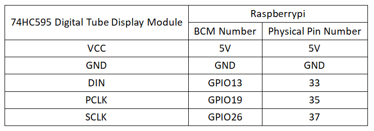
Raspberry Pi
Circuit Connection
Program Execution
Python
- Install the gpiozero library
- You can use the following command to install the library:
sudo apt update
sudo apt install python3-gpiozero
- For other systems on the Raspberry Pi, you can use the following command to install the library:
sudo pip3 install gpiozero
- Run the following command to view the GPIO pin definitions on the Raspberry Pi:
pinout
- Download the Raspberry Pi reference example, unzip the file, copy it to the user directory, and run it:
cd raspberrypi/30/python_gpiozero
python 74HC595.py
- At this point, you can see the Raspberry Pi running the program correctly. To exit, press ctrl+C.
- Command description: gpiozero.OutputDevice(pin, active_high, initial_value)
- Main parameters:
- pin: GPIO pin number
- active_high: Internal pull-up/pull-down resistor setting
- When set to True (default), on() sets the pin to High, and off() sets the pin to LOW.
- When set to False, on() sets the pin to LOW, and off() sets the pin to High.
- initial_value:
- If False (default), all LEDs are initially off.
- If None, the initial state of all LEDs is unstable.
- If True, all LEDs are initially on.
- Main parameters:
- For more commands, please refer to the gpiozero documentation
